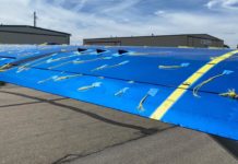
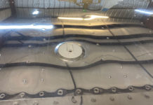
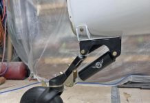
The metal area around the heads of the three bolts that hold the balance weight to the long balance support rib, is cracking around the heads. I reported this happening a few weeks ago at the GlaStar barbecue meeting at Sun and Fun. It happened on a GlaStar that was built in the same hangar as ours at El Cajon, CA. A repair has been made on that aircraft and we will make one on ours before it flies and also cracks. It is inevitable, because of the design that they will all crack in this area sooner or later.
Note: This is not a new situation.
Stoddard-Hamilton put out an ANOR that added a third bolt to this area. This extra bolt did not stop the cracking from happening eventually in the same manner but probably moved it down the line some flight hours.
This rib that the elevator balance weight attaches to, is unbelievably light, considering the job it does. However, I understand that the original tips were made of fiberglass, which was a lot stronger and gave a lot more stiffness and added strength to the weight attach rib, than the later tips made from the more flexible ABS material.
So what fix did they use on this other aircraft? I am informed that they made a doubler that covered the inner part of this rib and ran it from its tip, back to the elevator spar. This is a rather normal approach but I consider it a poor one in this case. The reason is, that they have now stiffened the rib back to the elevator spar but not beyond it.
This makes the area where the rib meets the spar, even more likely to crack and now you cannot even see it starting to crack, unless the tip is pulled, because the doubler hides the potential crack area.
I think the best quick fix is to just add a doubler plate, ( inboard side) of rib to a point ending beyond the weight attachment area a bit. If you are already dealing with some cracks, stop drill them. You might consider a thin large area washer under the weight attach bolt heads. Note: make sure you still have plenty of clearance between the weight rib and the end of the horizontal as the rib swings past the horizontal tips edge.
We are planning on doing the following: Making a doubler out of .032 aluminum that will start at the nose of the weight but on the outer side. On reaching the rear of the weight it will be bent 45 degrees inboard. When this bend reaches the face of the rib, it will be bent back 45 degrees and follow the inside of the rib, rearward. It will extend past the spar end, and a few inches beyond the rivets that hold the spar clip to the rib. The spar clip rivets will be drilled out careful so as not to bend the clip inside. The new doubler will pick up these holes They will be brought out to 1/8″ to accept cherry rivets. The area rearward beyond these clips will also probably need 1/8″ cherries. The rest of the forward area is open so hard rivets can be used. The weight bolts will be extended through the new outer doubler.
We will have to take 3 or 4 rivets out of the trailing edge to view the interior work and allow the drilling trash to be dropped out. The flat side of the new doubler, (at the outer weight face), will have small angles riveted to it top and bottom. These angles will lay flat against the ABS tips (top and bottom). They will contain two holes with nut plates that will match holes in the ABS. With screws in these holes, the whole weight area becomes contained as a box that is further supported directly by the ABS connection.
Note: Be sure to check out the balance of the elevator after the repair.


