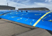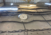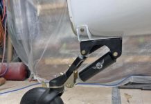
Tip fairing: You may need to cut the rear of the rudder tip fairing off if it is too long and glass on a new end.
–Jim Londo
Rudder counterweight rib alignment: Many people, including me, have had trouble with Step 10 in the rudder construction section of the tail manual. In this step, the builder uses three brackets to attach the counterweight rib to the forward and aft spars. As you are well aware, the placement of the counterweight rib is critical, as even a slight misalignment will make it very difficult to use the pilot holes that have been drilled in the skin. Many builders (including you) have suggested using the skin as a template for the proper alignment of the ribs and spars (SH Builder Support now recommends this method as well). This works well, but is a bit cumbersome and time consuming.
To properly align the rudder ribs and spars prior to drilling the counterweight rib brackets, I used double-sided tape to attach a piece of wide translucent paper (mine was graph paper used in drafting) to the inside of the rudder skin (this paper can often be found in art supply stores). With the paper taped to the inside of the skin, I sprayed the outside of the skin with a dark paint. When the paper was removed from the inside of the rudder skin I had a perfect template showing the precise location of each pilot hole. I simply taped the template to the spar/rib assembly and moved things around until everything was in perfect alignment (using translucent paper makes it easier to see the ribs and spars behind the paper). I then clamped the counterweight rib and its brackets in place and drilled the brackets and rib as specified in the manual. The whole procedure took less than an hour and when the skin was slipped into place the rib/spar alignment was as close to perfect as I’ll ever get! Hopefully future builders will find this of use! I’m now drilling the holes in the skin and things seem to be moving along pretty smoothly.
–William Renehan
Rudder counterweight rib alignment Part II: Sid, I submit the following report on one way to unduly complicate Bill Renehan’s excellent suggestion re Step 10, Rudder Assembly. Simply select the wrong type double-sided tape! In the past, I have used double-sided masking tape, which sometimes is labeled “carpet tape.” For this project, I purchased double-sided carpet tape at WalMart’s. It did seem a bit sticky, but I went ahead and used it to attach the translucent paper. “Attach” is the correct word! I worked for at least an hour (maybe more) removing the translucent paper (which looks like it went through a windstorm) and the tape (which stuck to everything in sight). I gave up on trying to save the paper – I simply worried about saving my rudder skin. This tape stuck so well that I believe we could use it instead of rivets to attach the skin! I then went to a local hardware store and found a roll of double- sided masking tape (also labeled “carpet tape”, but obviously not any more sticky than regular masking tape). This tape has about the right amount of sticking power, and can be pealed loose readily when the time comes to remove it. I lost about 2-3 hours total on this fiasco. It was my fiasco; mine alone. The technique is solid; the application went awry. Tell everyone to test stick and unstick their tape. Also remember that removing masking tape becomes more of a problem if it is left in place over a period of days.
–Joseph A. Colquitt
Rudder alignment: The rudder does present some “alignment challenges”. I jigged the rudder up, as per plans. In addition to immobilizing the trailing edge of the rudder at the tip and rib, I also ran a couple of pairs of aluminum angle on both sides of the rudder, from the trailing edge to the forward spar. At the trailing edge, the two angles were clamped together and then both angles (one on each side) were clamped to the forward spar. I used this set-up in two locations along the side of the rudder, in addition to the uprights called for in the plans. The idea behind all of this was to keep the skin straight from front spar to rear spar to trailing edge. The manual mentioned crimping the trailing edge if it wasn’t the proper contour. If this is done after the rudder is constructed, there is no place for the skin to go when the radius is reduced. In other words, if you have anything but a straight line from front spar to rear spar to trailing edge, you’ll have a bulge. If you have to reduce the trailing edge radius, you’ll have a bigger bulge.
–Bob Skinner
Jig: Didn’t really like the SH jig and if I had it to do over again I would make another upright board as a mirror image of the SH suggestion with the rudder between them and run the strings between the boards. I was very uncomfortable with the string setup in Figure 9, although everything worked out ok. I was also a little uncomfortable with 3/32 rivets in some of the brackets and added a 1/8″ rivet whenever I felt it was needed. Maybe a bunch of hooey but I feel better. Seemed to have to do everything associated with the counterweight rib twice. (Speed reader). I wonder how many other rudders will have the forward and rear spars flush riveted.
–Mo Brooks
Rudder Hints:
- If it’s not already too late, build the horizontal stabilizer first. It’s much easier and will get you “warmed up” for the rudder (which is more challenging to rivet). This was Cal’s idea and we think it’s a good one. (Thanks Cal).
- Take time to build a good jig as per the manual. We used fishing line strung through the hole in the yoke and the counterweight rib and checked it religiously during drilling.
- If at all possible, get help bucking. Solicit someone with small hands, who doesn’t mind the odd scrape and bruise in the line of duty. When bucking the rivets inside the forward skin, I actually taped a bar to my hand so I wouldn’t have to grip the bar (since my thumb got in the way).
- Put masking tape on your bucking bars (to protect scratches on the interior corrosion-proofing) – except, of course, where the shiny part of the bar is supposed to contact the rivet.
- Have lots of different bucking bars. We’ll be lurking around the bucking bar bins at Oshkosh, looking for bargains.
- Drive each and every rivet with due care. We decided that we don’t want to be caught in turbulence some day and start wondering about whether or not those rivets in the back will hold.
- Use a rivet puller with a swivelling head for doing the impossible job of pulling the blind rivets in the counterweight rib – aft spar bracket. After some swearing, we found this worked pretty well. I think this was the dreaded “step 20.h” that was discussed a while ago.
- If you have a pneumatic squeezer, use it when you can. We just love ours. So precise, so quiet! Make sure you have all the available heads. It’s expensive, but we assume we can sell it to another builder once we’re done. Unless we get too attached to it, of course).
- If we had to do it again, we’d drill out the holes along the forward edge a bit smaller, prior to dimpling, since the process of dimpling enlarges them just a bit.
- And finally – if in doubt, drill out.
–Kathy Sutton
Rudder rib positioning: Here is an alternate to the graph paper and double sided tape technique for the rudder rib positioning. At the Artist supply store I purchased a large sheet of clear acetate, and some 1/16 inch Forma a Tape. I simply taped the acetate onto the rudder skin with regular masking tape. I then laid out lines on the template using the forma a tape. This created intense black lines on the clear template. The template is about the thickness of the alum skin so I just laid the template onto the side of the rudder while it was in the jig (fixture) . Works like a charm. The forma a tape or maybe it is called forma a line is a tape used for graphic artists for chart layup. It comes in all colors and widths down to 1/32 of an inch in width. I used 1/16 because it looked like the 1/32 would be hard to handle.. This line tape can also be coaxed to stick to alum parts if they are oil free and you do not handle the tape too much with your fingers. Someone has suggested this previously, I think.
–John Steichen 5467
5/26/98 Rudder spar positioning: I’ve finished the rudder and wanted to pass along a couple of lessons before I forget the important ones. I read through the archives thoroughly before starting. Well worth the time and very much appreciated. Many builders have had trouble positioning the spars and ribs before drilling (step 10). I used heavy drafting film (acetate) to copy the holes from the skin for a template. Double sided tape is not necessary if small holes are snipped in the film or paper and regular tape is used across the holes and at the edges. When the film is lifted up the masking tape pops loose. I put the film on the inside and poked a sharp awl through the holes. After removing the film, just connect the dots with a ruler. The advantage is that the film is strong enough to be clamped right to the side of the spars and ribs while positioning and shows any misalignment easily. It occurred to me that the reason that the parts were so hard to align is that gravity causes the forward spar to sag at the clecos (like a swayback horse) between the yoke weldment and the forward spar. After attaching a line (to a rafter) to pull the weldment/spar joint up slightly I found the root rib and counterweight rib became parallel at 80.1degrees (in my jig, which my digital SmartTool module told me). A minor improvement, which came after a couple hours of fighting the parts, but worth passing along.
–Michael Harfst


