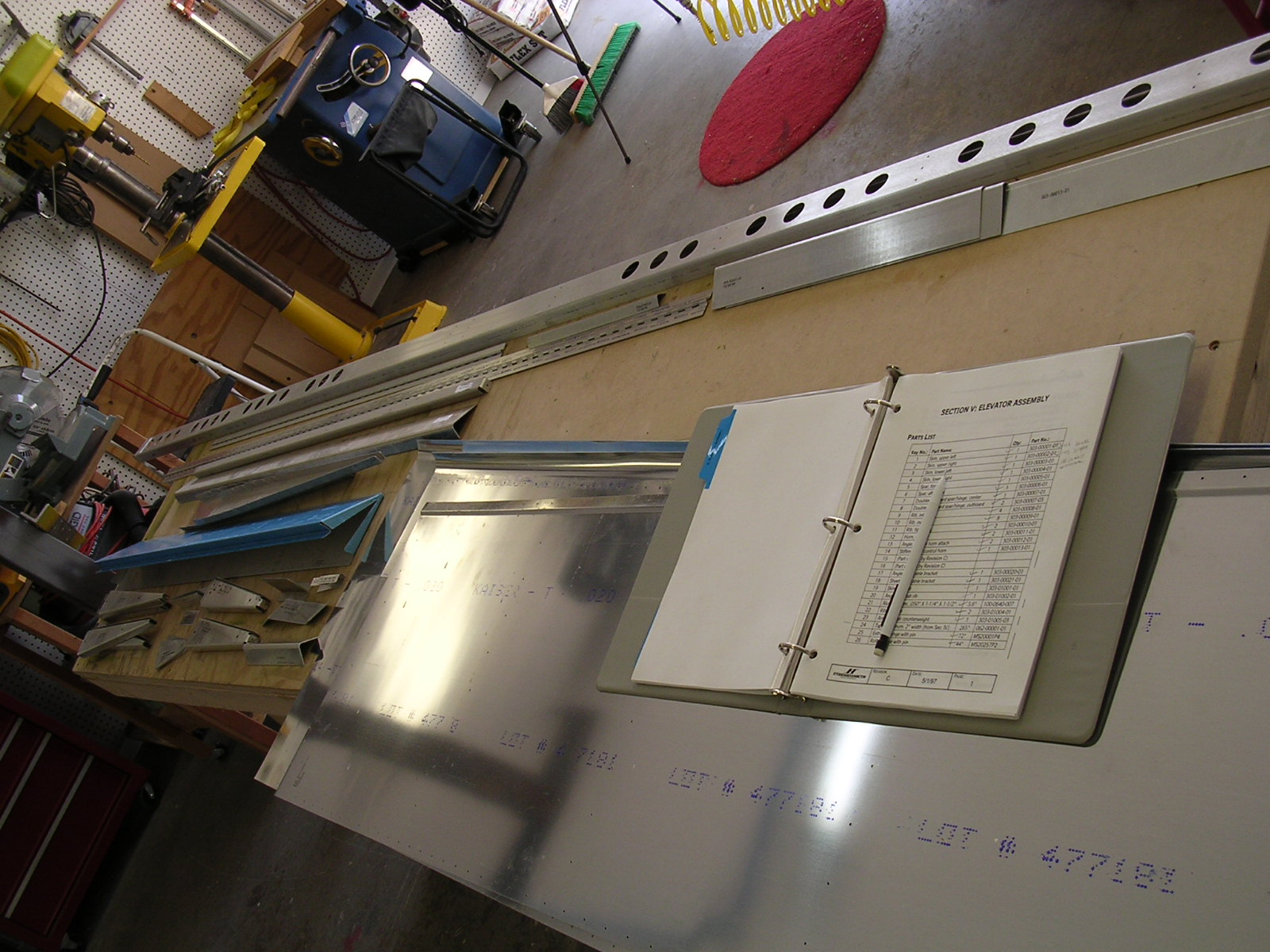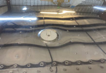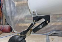
Keeping twist out of the aft elevator partial spar: There is a discontinuity between the aft edges of the elevator respective to each end of where the trim tab fits. If I did it again, I’d use a long angle iron or else carefully mounted angle irons along the aft elevator partial spar. I would then drill and cleco the trailing edge skin before drilling the rest of the skin.
–Roy Kokenge
Rudder Aft Partial Spar: I have had some real difficulty installing the trim tab hinge. The problem stems from the poor fit of the aft partial spar, which in turn is caused by the ribs being too long. I finally managed to get thru to the S-H customer support folks. Here’s what they recommended:
When initially assembling the elevator, don’t trim the aft partial spar, or attempt to force it flush with the skins. Instead, allow the spar to stick out. When it comes time to install the hinge, draw a centerline down the hinge, ignore the pre-punched holes in skin, and drill new holes between the pre-punched holes which place the line of rivets in the center of the spar flange. That is, mount the hinge to the spar in the proper manner, and don’t worry about where the holes end up in the skin. I’m going to have to replace my aft spar, which means drilling out to rivets that connect it to the rest of the elevator assembly. I’ve been given the OK to use blind rivets (1/8″) to re-attach the spar to the ribs.
BTW, I have had some trouble riveting the hinges on to both the spar and the trim tab. Here’s what I did to make it work: I’m using an Avery hand squeezer with a one-inch no-hole yoke to rivet the elevator side hinge. I taped a hard metal shim to the tip of the yoke, allowing the tip to clear the hinge knuckles, and squeeze the rivets to the proper length. On the trim tab side, I used an Avery dimpling frame, and I made an offset rivet set out of half-inch diameter cold-rolled steel bar stock. Place a cupped rivet set in the dimpling frame anvil. Then place a ten inch length of the bar stock into the dimpling frame’s guide bushing. Make sure that both ends of the bar stock are reasonably flat and smoothe. Use a mallet to bang on the bar stock, and mash the tail of the rivet to specs. The bar stock must be relieved to fit around the “bump” in the lower surface of the trim tab. I cut away about half the cross section of the bar for a length of an inch.
–C.A.P. Smith
Elevator ribs too long fix: BEFORE drilling the left-bottom skin for the elevator (which is the first to be drilled), identify the four ribs that connect the forward (main) spar to the aft (partial) spar. These four ribs are too long – therefore, they push a bow in the aft partial spar and problems exacerbate as the drilling and assembly continues. The solution – shorten the four connecting ribs to the correct length. You did this while building the horizonal stab – remember cutting the forward flanges from two ribs because of the spar doublers? Same here, even though the spar doublers aren’t the problem. Here, the problem is ribs that are too long. But then that’s the same problem in one way of looking at it. Correct it the same way. Cut the forward or aft flanges from the ribs and replace those flanges with angle.
One way to do this is to cut away the flanges that connect the four ribs to the forward spar. Make replacement flanges that are longer than those cut away. Draw your centerline on the partial aft spar. (I use red Sharpie pens because red marks show up better than black ink.) Now install and drill the lower skin with the four ribs connected with clecos only at one end (the one with the flange). Drill the aft spar only after straightening and squaring it with the prepunched pilot holes on the trailing edge of the skin. You now have a straight aft partial spar with the holes in the middle of the spar. Now cleco the replacement flange to the aft partial spar, then drill the rib and replacement flange to the correct length and cleco them together. The rib is now the correct length so you can drill the skin prepunched holes over the four ribs.
If you don’t follow this suggested approach, let me know and I’ll try to clarify it. Basically though you’re doing what you did with the horizonal stab (shortening ribs) to correct a problem with the elevator (four ribs too long resulting in a bowed aft partial spar – which causes additional problems later on when installing the trim tab hinge).
–Joseph A. (Joe) Colquitt
Elevator control horn: I had trouble with the hole layout on the elevator control horn attach angle. As spec’ed, there is a strong possibility that edge clearance cannot be met at the last hole on the angle flange that attaches to the elevator. Cal suggested reducing the spacing between the five holes to 15/16″. That solved the problem and does not result in a conflict elsewhere in the structure. He also said that the hole spacing on the flanges attaching to the control horn should be reduced to 11/16″ horizontal spacing between all holes. No change in the vertical measurements is reqired. This change preserves edge clearance on the control horn itself.
-Bill Smith
Elevator: When laying out the rivet patterns for the Forward Spar/Hinge Doubler hole locations as shown on page 7 in the manual, be aware that you may find that some of these holes will violate edge distance requirements on the lightening holes. Before drilling make sure that your marked locations line up visually between the lightening holes on the spar. Luckily, I found this out before drilling. Also, the Rib/Control Horn Stiffener dimensions given on page 13, figure 5 (specifically the 1-5/16″ value in step 5) will cause you to cut a piece that is too narrow to allow proper rivet spacing on the stiffener. Again, eyeball the thing before cutting!
–Tom Fleming
Getting a perfect match (elevator to horizontal stabilizer): I have since completed the elevator and HS using the mentioned sequence and it worked just fine. I also temporarily flush riveted the hinges in 2 or 3 places for each hing to the elevator prior to drilling the top skin. The horizontal stabilizer part of the hinge was clecoed in place. This allow me to jig the elevator directly to the horizontal stabilizer, make sure that the weight ribs were perfect, and that the trail edge was straight, PRIOR TO THE FINAL DRILLING OF THE TOP SKINS. Once you are done with all the drilling you can drill out the flush rivets that are connecting the spar to the hinge and remove the hinge for priming. When I got to the hinge instructions there was no sweat. It was all done.
–John Steichen #5467
Trimming the Elevator Spar: The plans call for trimming the forward spar and skin, where the hinge is to be riveted, to 3/8 – 5/16 inches from the rivet hole centerline. A fellow contractor, that was previously employed by Lockheed, said that they routinely use routers to trim aluminum edges. I used a carbide edge router bit (one that has a bearing at the base) and a 6 foot piece of 1/2 x 1/2 x 1/8 inch aluminum angle. The angle was clecoed every 8″ below the spar flange that was trimmed. I used the patterned holes on the skin but used #40 bit, so that the holes could be re-drilled to size for the hinge rivets. The aluminum angle acted like a fence preventing the bit from going beyond its intended depth. I had to remove/re-insert rivets as the router was passed over the surface of the elevator. Watch out for the ends where you can’t cleco. Without a cleco every 8-12 inches the aluminum angle will flex. You might consider an undersized flush rivet on each end or do that section with a file. Don’t forget to put on the safety glasses.
–Delbert Johnson
Elevator rib flange spacing: I am working on the Elevator and am having problems with edge spacing. I will be modifying several ribs with bent flange doublers to overcome offsets up to 1/8″. I have received information from SH and from other builders. SH is aware of the problem that the pilot holes in the short and long ribs are not on center to the flange. Furthermore the rib flanges for the spars is longer than the ones for the skins. CHECK OUT YOUR ELEVATOR RIBS BEFORE YOU BEGIN. Here are some suggestions:
- Measure before drilling. Determine how much error is in the ribs before starting. Mark the rib flange centerline to ensure enough E.D. for 1/8″ rivets. My skin and spar hole spacing matched so I determined the only error was in the ribs.
- Determine if the rib marked centerlinecan be clamped in position (without clecos) to match the spar and skin holes, then drill to #30 with a clean hole in the rib flange to the forward spar. The ribs have a 1/16″ pilot holes so there may be room. I could not do this because I found out too late when I was positioning skins.
- If you determine you cannot offset the drilling to get a clean hole, you will have to fabricate bent doublers for the flanges that will nest inside the rib. I made mine from .020 stock to allow (4) 3/32 rivets to the web near the large flange and (2) 3/32 rivets to the web near the small rib. When laying out the holes for the doubler/spar web, make sure you maintain edge spacing to the rib tooling hole. My spacing was approximately 1/4″. The only problem I see is that there is an elongated hole sandwiched between the doubler and the spar. I dont think this will be a problem in that the ribs are only .020 thick.
–Gus Gustavson
Elevator tip rib counterweight and fairings: Looking at the elevator tip ribs, in my opinion they are not strong enough. There is almost 4-5 lb. hanging way out at the end. You will notice that the rib is very flexible. I don’t think the lead is a good idea. Look at the recent service bulletin addressing the need for a 3rd hole for the bolt. You can tighten down bolts with lead under it and it will probably work its way loose again.
To solve this problem of the bolt situation I used a piece of 18 inch long aluminum angle 1 ½” X 1″ X 1/8″. The 1 ½” side is vertical and the 1″ side is at the bottom, like the letter “L”. The vertical side goes against the tip rib, running from about 3/8″ from the forward edge of the rib to about 4″ aft of the hinge line. The rib and stiffener were then drilled with a #30 drill 12 places in the stiffener fwd of the hinge line. The tip rib was then dimpled for a flush rivet and the stiffener was countersunk to match the dimpled rib. Aft of the hinge line I drilled #30 holes for APQ-44 pull riveted since my ribs were already installed. In the back side of the stiffener aft of the hinge line where it lays on the 3/32 rivet heads (if tip rib was previously installed) use a 3/8 drill and relieve enough material form the stiffener to clear the 3/32 rivets so stiffener will fit down flush against the tip rib. It would be better to do this while building the elevator.
After the corrosion proofing (anodizing) the angle was attached with 1/8 flush rivets. Before attaching the angle lay out 2 #10 holes for bolting the counter weight on and drill, dimple rib, and counter sink the angle. I also drilled a # 10 hole in the bottom flange of the angle centered fore & aft between the other #10 holes. This extra hole will receive a bolt down through the counter weight and bottom flange of the angle while the flat head will be in a similar position as called for in the manual. I didn’t use the lead but instead used a 2″ round piece of solid brass with 1 side and the bottom milled down so it fit up against the angle. Brass is very dense, is heavier than steel, and won’t deform like lead. I didn’t worry about the extra weight of the 1/8″ aluminum angle because most of it is fwd of the hinge line anyway and that’s where the counter weight will go.
I also didn’t like the cheap Cessna looking tip fairing for the stab and elevator. I took the ABS ones supplied and cut them in half length ways and duct-taped them together. That became my mold to lay up 2 layers of BID cloth on the inside. After it cured I removed the tape and pulled the mold off my new glass fairing. I put a flange on mine so the glass goes under the elevator skin aft of the hinge line with the skin dimpled and the nut plates on the fairing. Forward of the hinge line the nutplates are on the rib. I also did the same for the rudder tip fairing but bonded it into place and faired it smooth to the skin.
It was a lot of work but it helped the looks over the supplied fairing.
–Don Muhlnickel
Tip fairings: We were sent a set of ABS tips for the stabilizer and elevator. Of course the instructions in the manual are for the older style tips. You will have to trim about 3/4 of an inch off of the counterweight ribs to get them to fit. By this time you will see that the holes for the counterweights are way out and into some mighty thin looking material. Since we are about to add some three pounds of lead here anyway, we opted to install a doubler on the inside of the counterweight rib. Make sure that you use PLENTY of nutplates and screws to hold the tip fairings on. Cessna has long used the same crappy material, and they usually crack in the first ten days of the airplanes life.
–Tom Lempicke
Balancing the elevator and trim tab: The manual shows you balancing the elevator first, and then the trim tab. This will not work, since you are adding nearly a pound of weight to the trim tab after you have already balanced the elevator. Do the trim tab first, and then install it on the elevator to do the balance on it. A much easier way to do the balance on the elevator is to turn the stab/elevator assembly sideways on your table and suspend a soda can from each balance pointby a piece of safety wire. To get it at the exact point of balance we screwed a piece of a paint stir stick to the two holes you were told to drill in the counterweight dribs, and drilled a small hole in the center. Run the safety wire through this small hole. Pour lead shot (or nuts and bolts, or whatever) into the cans about equally. When it balances weigh the whole mess, including the paint sticks, nuts and bolts to attach them, safety wire, etc. And divide by two. This is what each weight must be.
–Tom Lempicke
Sequencing elevator & electric trim instructions: So far my construction has progressed very easily from the HS, then the rudder, and now the elevator. The whole process has been fairly straight forward, but I have found the intermixing of the electric elevator trim instructions, with the main plans very confusing. The plans sort of tell you when to go the the option plans, but the option plans leave you in the dark as to when to return to the main plans This is the sequence I finally figured out after hours of study:
- Prodeed normally up to step 5 in the elevator main plans
- Go to Electric trim option (ET)
- Fabricate then drill holes on Rib/control horn stiffeners (ET1 & ET2)
- Do step 3 & 4 (ET3, & ET4)
- Return to main plans . Do Steps 13,14, 20,21, 22, 23, 24
- Position and drill the lower right skin Steps 25,26
- Go to Electric Trim Option do Step 5 (ET5)
- Go to Main Plans
- Do lower left skin –steps 28,29,30,35,37
- go to Electric Trim Option
- Do Steps 6,7,8 &9
- Go to Main Plans
- Do Step 39, 40, 42.1,43 & 44 (Do all your priming at this stage. I think the servo is actually installed after all the riveting and the trim tab has been fitted with the hinge.)
- Go to Electric trim option instructions –Do Step 10
- Return to Main Plans Do Step 45, 50,51, 52
- Go to Electric trim option do Step 11
- Return to Main Plans
- Do Step 54,55,56
- Then continue with the trim tab instructions in the main plans. etc etc.
Whew. If anyone sees any problem with this sequence please say something. I hope this helps others, and does not lead them astray.
–John Steichen 5467
Amplification of John Steichen’s above sequence:
| Main Elevator Instruction Steps | Electric Trim Instruction Steps | |
| 1-3; skip 4; 5 | ||
| 1-2 | ||
| 10-14 | ||
| 3-4 | ||
| 20-26 | ||
| 5 | ||
| 28-30 (skip 31-34) | ||
| 35 (skip 36) | ||
| 37 (skip 38) | ||
| 39-40 | ||
| 6-9 | ||
| 42.1-45 | ||
| 10 | ||
| 50-52 | ||
| 11 | ||
| 54-92 |
Note that the main instructions advise returning to step 43 and not 42.1, but I believe this is an error in the manual.
Note also that there are still Electric Trim steps 12-28 to deal with; I believe these are referred later in the manual (perhaps Section X, Final Systems Installation?).
–Arlo Reeves 5489
Elevator hinge alignment: In positioning the three elevator hinges today, I accidentally noted that whilst I could move the halves on the elevator itself back so that the gap at the knuckle was under the spar by 1/32, as per the manual instruction, the hinge was actually riding up on the bend where the flange bends to form the web.Thus there is a gap between the hinge and the flange –not at all desirable I suspect. In fact, because of the width of the hinge half, it is not possible to meet the 1/32 back condition without this problem, which could easily be missed.
I took 3/32 off the back of the hinge half then radiused the appropriate corner (like we did for the spar caps of the stabilizer). This allowed the hinge half to sit flat in position. I think it would be desirable to check this again after the hinge has been drilled, in case in the lining up process it moves a bit from the initial clamping, particularly if you are a bit miserable on the first 3/32 removed!
–Kiwi Pete
Elimination of counterweight: For we who have elevators complete, S. B. 40 gives us four options regarding the counterweight on electric trim tabs.
- Leave it in place.
- Remove the lead weight only.
- Remove the weight and the arm.
- Remove the weight, arm, and replace the control horn.
I elected to remove the trim tab counterweight arm and leave the original control horn in place. When I drilled out the fasteners to remove the c/w arm, my control horn looked like swiss cheese. S-H must have decided this newly ventilated control horn would be structurally sufficient.
To make things look a bit better, and to increase the strength of the horn, I elected to fill the holes. By very slightly countersinking both sides of the holes, driven rivets provide adequate load paths, (though not as good as if the horn hadn’t been drilled).
Caution: Countersink very shallow-only enough to provide a toe hold for the rivet. After driving, the rivet will be high on both sides.
After mushing the countersunk rivets I removed excess material (both sides) so that the newly driven rivets are flush with the horn. When sanding down the rivets, be careful not to remove any material from the horn. Treat and prime the horn and you’re good to go.
When removing the counterweight arm, the service bulletin further allows you to trim the existing horn to match what a new one should look like. My rivet pattern placed the trim line through some newly filled holes, so I couldn’t to trim my horn. I would strongly suggest observing normal edge distance margins to holes, even if they’re plugged per above.
–Scott Fifield, #5334
Trim tab Z rib fabrication: I found that the “Z ” ribs were near to impossible to get correct. In the end I made a one piece replacement for the 4 parts that make up the “Z” ribs. It looks like a tapered hat section. It took a couple of tries to get a good part made, but in the end it saved time and looks much better than the original setup.
–Mike Thompson


