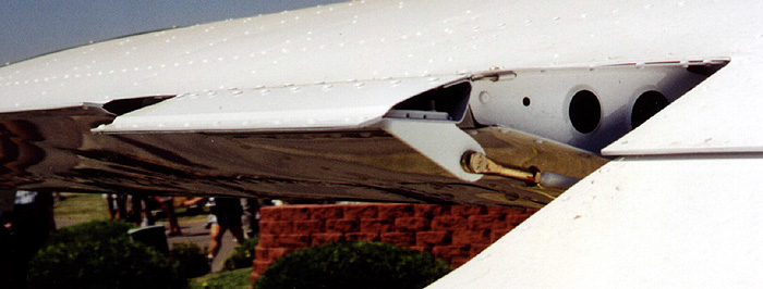
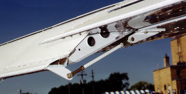
The aileron servo helps reduce stick forces in roll.
BILL OF MATERIALS
1 12″x12″ .032 aluminum sheet [2024 T3]
88 3/32″ pop rivets [Cherry MSP-32]
24 1-1/4″ aluminum extruded hinge [MS 20001 P3]
16 1″x1-1/2″ x 1/8″ aluminum Angle [2024 T3]
2 terminal ends [AN665-21 R] /clevis pins and cotter pins
2 rod ends [10-32 female end, 3/16 Bore] / 3/16″ bolts and cotter pins
26 10-32 threaded rod [steel]
10 3/16″ id tubing [steel]
4 10-32 jam nuts
10 8 –32×1/2″ bolts [AN526-832R-8]
10 8-32 washers
10 8-32 [AN364-832 A]
CONSTRUCTION DETAILS
STEP 1: Lay out cutting lines
- use drawing to layout top, bottom and end cuts
BEFORE CUTTING – measure the vertical distance between the top and bottom surfaces at the angles described by the top and bottom cutting lines, mark these dimensions on the drawing so that you can be assured that the tab and aileron surfaces will be “fair” after the assembly is complete. The dimensions should be approximately 15/16″.
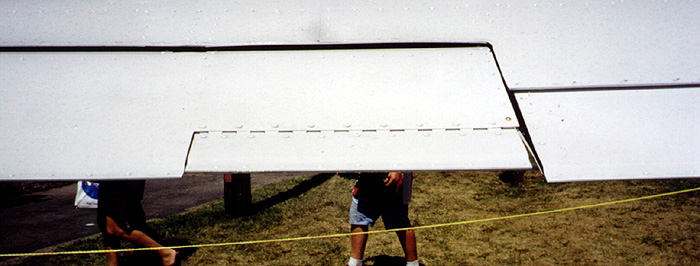
STEP 2: Cut the tab area from the upper and lower surface of the aileron
- for constructed ailerons it will be helpful to use the Dremel tool with a cut-off wheel to remove the material that will become the new servo tab
- for unconstructed ailerons it may be possible to remove the servo tab material with a straight pair of tin snips or duck bill snips, the important consideration here is to make sure that you do not distort the aileron and/or servo tab material as a result of the cutting operation
- the first cut on the upper surface is 3″ from the trailing edge
- the first cut on the lower surface is 2-13/16″ from the trailing edge
- after cutting the servo tab material from the aileron it will then be necessary to cut the 1/4″ waste from the top surface and 1/2″ from the bottom piece
STEP 3: Rivet the two servo tab pieces together
- if the aileron has already been constructed ignore these instructions and move on to STEP 4
- the best way to make sure the tab will fit after the forward spar is attached is to fasten the trailing edges together, follow the instructions provided in your assembly manual for the ailerons
STEP 4: Form the forward and aft spars
- use hardwood forming blocks or a sheet metal brake to form the forward and aft spars
- the spars will “close out” the trailing edge of the aileron and the forward edge of the servo tab
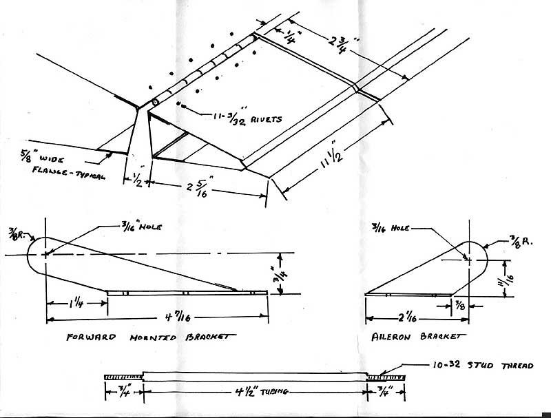
- the angles necessary for the spars can be seen in the side view drawing of the servo tab
- make sure you provide at least 1/2″ for the rivet flanges (5/8″ is recommended on the drawing)
- USE THE DIMENSIONS YOU NOTED FROM YOUR AILERON TO LAY OUT THE NEEDED SPARS, remember to deduct the thickness of the hinge that will be installed between the lower surface of the upper skin and the upper surface of the spar
STEP 5: Clamp the spars and the piano hinge together in preparation for rivet hole layout
- place the forward spar between the upper and lower “skins”
- slide the piano hinge between the upper surface of the spar and the lower surface of the upper “skin”
- layout the rivet holes approximately 1″ apart on both the upper and lower surfaces (Remember to provide a hole for the attachment of a hinge pin clip as you did on the elevator surface)
- drill holes for the 3/32″ cherry rivets and cleco the parts together
- next lay out the holes on the servo tab and insert the rear spar between the upper and lower surfaces
- drill holes in the lower aft spar and tab surface and cleco together
- next, slip the servo tab onto the piano hinge which is now attached to the aileron
- after carefully aligning the tab with the cut-out on the aileron, clamp in place, drill and cleco the servo tab to the aileron
- after you are satisfied with the temporary assembly disassemble, clean, deburr, and prime the interior surfaces the servo tabs can now be “pop riveted together
STEP 6: Construct the forward and aft push-rod mounting brackets
- it will be necessary to re-cut the aluminum angle stock to 1-1/4″x3/4″ before beginning to shape the mounting angles
- THE CRITICAL DIMENSIONS ARE THOSE RELATED TO THE HOLES REQUIRED FOR THE MOUNTING OF THE ROD ENDS AND THE TERMINAL ENDS. IT IS IMPORTANT THAT THESE DIMENSIONS BE CLOSELY HELD SO THAT THE PROPER “THROW” IS OBTAIN
- MAKE SURE YOU MAKE TWO PAIRS OF EACH BRACKET—THE ORIENTATION OF THE BRACKET IS IMPORTANT
- the three mounting holes shown in the side view of the forward bracket (the longer one) must be laid out to match the rivet holes that are found in the lower surface of the cove rib located at the outboard end of the flap assembly. The brackets will be installed even with the trailing edge of the cove rib/lower “skin”.These three holes are drilled for the 8-32″ bolts which will be utilized to mount the brackets to the wings. The nuts and washers can be installed through the lightening hole.
- the aft servo tab brackets are attached even with the forward edge of the servo tab with 8-32″ bolts, washers and nuts
To view the orientation of these brackets, see drawing above
Step 7: Construct the push rod tubes
- the two push rod tubes are cut to 4 ½” long (update: change to 4 5/8″ or adjust total length hole-to-hole to be 8″ while assuring that you have the correct number of threads to safely thread on the rod and terminal ends)
- four pieces of 10-32 threaded rod are cut to 1 ½” long
- insert 3/4″ of the threaded rod into the end of the ¼” od tubing
- silver solder or weld the threaded rod into the tubing
Step 8: Fasten the terminal and rod ends on the push rods
- install one rod end, one terminal end and jamb nuts on each of push rods
- adjust the fittings so that the center to center measurement is 8″ with some adjustment still possible at each end of the rod
Step 9: Assemble the servo tabs and make necessary adjustments
- THE 8″ C-C MEASUREMENT SHOULD BE VERY CLOSE TO THE CORRECT LENGTH NEEDED TO NEUTRALIZE THE SERVO TAB WHEN THE AILERON IS ALSO LOCATED IN THE NEUTRAL POSITION
- move the aileron to the full up and the full down positions, check for any interference from the push rod assembly
- the full throw of the aileron should not be curtailed by the throw of the servo tab
- the full throw of the aileron should cause the servo tab to be deflected approximately 3/4″ in each direction
For further reference see the Aileron Servo Tab Instructions from Glasair Aviation. The part number is 921-06100-01 and the kit can be ordered from the factory.
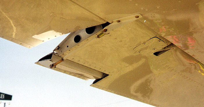


Are servo tabs installed on both ailerons or will one do the job?
Just one.
Mine has this mod on both ailerons (i am not the builder) and they are still very heavy.
The document linked above is for a single longer 24″ version rather than the one pictured; which seems to be shorter version like the ones on my plane which are about 6 inches on each side. imho