- Version
- Downloads 171
- File Size 266.58 KB
- File Count 1
- Create Date October 23, 2016
- Last Updated October 23, 2016
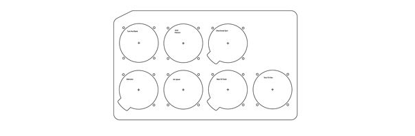
The avionics and instrument drawings show hole locations and hole sizes. They also show behind panel clearances in red.
David Walker's Panel Drawings notes:
Advertisement
- These panels are suitable for the SH-supplied Future Vision panel
- With the right post-processor you can use these drawings for laser cutting. I suggest thicker material (2.5 mm min) than supplied by SH as this is a full IFR panel & contains a lot of components - too much for the flimsy SH panels
- Check holes of SH supplied circuit breakers - some may not be the same diameter
(particularly the 60A which may be not Klixon)
Attached Files
| File | |
|---|---|
| Glasair_panel_drawings-1.zip |