- Version
- Downloads 66
- File Size 196.39 KB
- File Count 3
- Create Date January 14, 2022
- Last Updated January 14, 2022
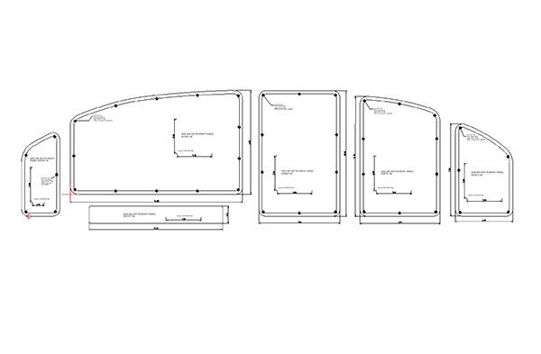
CAD drawing for the Airlink composite instrument panel. Confirm fit by printing on paper and cutting out the templates before making inserts. There are variations in the instrument panels, and small adjustments may be needed.
CAD and PDF files provided. Assemble the PDF printouts using crop marks on each page.
Advertisement
Attached Files
| File | |
|---|---|
| Airlink Panel Inserts.pdf | |
| Airlink panel inserts (Boyd Walker).dwg | |
| Airlink Panel Inserts (Omar F).dxf |