Transponder ground plane: Make your aluminum ground plane for your transponder as large as possible for effective use. I placed mine under the pilot’s seat.
–Jim Londo
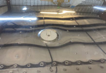
Transponder ground plane: Our experience with Glasairs is that a small ground plane did not work very well. We have had much better luck with a larger ground plane(read as large as possible) with the corners rounded off to a 3 inch radius. Pop rivets at 6 inch intervals around the edge are sufficient to hold it in place with ones as required in the middle to prevent oilcanning. When they go under the cage tabs they can be attached directly there with star washers and then you will have a much bigger ground plane.
–Cal, Stoddard-Hamilton
Ground plane: Install/screw a piece of ~.016 (thickness doesn’t matter except for weight) aluminum directly under your cage/seat pans-between the cage attach points and the shell- mine is 20″ x width of flat belly of fuselage. This will be the ground for my transponder and COM2 transponder will be an external blade type. COM2 will be an external belly whip antenna. Com1 is in vert stab. NAV1 GS1 NAV2 and GS2 will be connected to a quadraplex connector then to a set of “cat whiskers” on the vertical stabilizer (I have found no other way to do this internally). Marker beacon will be a copper strip internally aft on the fuselage belly, AM/FM radio will be similar. GPS has to be on top of the fuselage.
–Dan Dudley
Bigger is not always better: The most popular and least expensive transponder antenna is is the steel stub which in reality is a quarter wave vertically polarized antenna. The most effective ground plane is a disk of .03″ aluminum 5″ in diameter. The disk should be epoxied to inner skin (under the seat is OK), length of coax should not exceed 8 feet, always use good grade of RG58 (foam dielectric is a no-no). Antenna should mount to aluminum disk not glass skin! By the way I am a partner in a GlaStar kit, an avionics engineer, and own and operate a FAA repair station and we specialize in custom avionics Installations.
–Larry W. Johnson
Ground planes: Not to be too cheap, but when it came time to install the transponder and DME ground planes between the shell and cage, I had a problem with the $15 may Ace Hardware wanted for a 2 x 3 foot piece of aluminum. After all, I only needed 2 pieces of 250 square inches each. I was just about ready to break down and realize I really am as cheap as my kids say, when I saw 2 foot sections of 4″ aluminum ducting material…and only $2.39 each! They are just the right size when the fluted end is cut off, they measure 22″ x 13″ (286 sq. in.). They fit just perfectly under three of the shell attach points under the seats, and leave plenty of room to work on the shell dorsal seam. S-H says to tie them together with a conductor, and they will work even better.
–Tom Eggers
ELT antenna ground plane:
> The ELT I bought comes with an antenna that I will mount in the aft section of the fuselage but it calls for a ground plane I think about 30 inches in diameter. I’m not sure where I’m going to put this. If I run strips of copper tape, does it matter if the strips run from the bottom of the fuselage up along the sides. Any ideas?
As a designer and installer of radio systems in airplanes, I can identify with the desire to have 15″ of clear sheet metal in any direction much less a full circle. Haven’t come close to that idealism since leaving Cessna in ’69 – that cabin top skin makes for about the most idealized antenna systems flying. So, we learn the art of compromise. The ELT is probably the last radio to worry about. According to a recent article in AOPA Pilot magazine, the ELT system can only be counted on to function a very low percentage of the time. I’d mount it on centerline with a minimum of four “radials” of the copper tape you mentioned. The tuned radials are really effective only if they’re not in close proximity to detuning conductors like control cables, wiring, structure, etc. so their exact length is not critical either.
–Bob Nuckolls – AeroElectric Connection
Prefab internal antennas: Another alternative would be to use one or more of Bob Archer’s antennas. He makes a series of well designed folded dipoles for composite aircraft, both VOR & Com. He also has a transponder/DME antenna that can be mounted internally. They are available from ACS, but Jim Ayers (LesDrag@aol.com) has them available for a lot better price (or used to–I think, maybe). Both he and Bob Archer will also sell direct for $55. Bob also has a marker beacon antenna for $25.
–John Top #5372
VOR antenna:
>Is there a VOR antenna that goes in a single wingtip. or is it necessary to put a balancing element in the other wing tip?
Call Bob Archer 310 316-8796. His wingtip antennas are designed to work in a single wingtip. His SAA- 03 or 04 should fit the GlaStar tip. The RV guys swear by them. My current thinking is to use his SA-0007 & SA -0008 (they’re the same except for overall length & matching devices). One installed vertically in the HS for com & the other bonded to the bottom of the Fuselage behind bulkhead “A” for VOR. I have some articles he wrote on antennas for composite aircraft if you or anyone else wants them.
–John Top
Com antenna placement: I decided, for several reasons NOT to go with the comm antenna glassed into the fin. I bought a Cessna type antenna (Chief: PN CL-121, Aircraft Spruce PN # AV-529–around $80) and installed it as follows. I cut a piece of .032 about 16 inches square, bent it to mount against the top of the fuselage shell forward of bulkhead B, Then, after the curve was formed (to fit fuselage) I drilled all my holes in it for the mounting bolts/screws of the antenna. Then I drilled a hole through Bulkhead B for the antenna to extend through it into the upper fin area. (At installation, I secured the antenna with some silicone caulk–RTV so the glass of the bulkhead would not chafe the antenna) Thus it takes on the “attitude” (angle) very similar to what it would be if it were mounted on a Cessna and fits nicely inside the fin. Then I mounted the aluminum (which serves as my ground plane) to the top of the shell by cutting some 1 inch holes through it and putting some small glass cloth “patches” over the holes, thus glassing it to the inner fuse. shell. This way, I can replace the antenna some day if I should ever need to. Also, as I understand it, the other type antenna radiates in a cloverleaf pattern, making some areas of good reception and some not so good. My type of antenna radiates in a perfect circle. I communicate well in all directions, and to date have reached out 75+ miles that I know of. (airborne) I can talk to my unicom from inside my steel hangar with the doors shut. I was able to do the same from my shop at home several miles from the airport.
–Paul Hansen

Antenna installation: I have the glideslope antenna mounted to the windshield. It is the copper tape dipole. Each “leg” is 8″ long and the two legs are separated by 1/2″where the coax is connected. The coax solders directly to the tape. Center conductor to one side and the shield to the other. It does not make any difference which side is what. The antenna is mounted horizontally, with the center of the antenna (where the coax connects) being 2″ from the windshield joggle. Each leg slopes aft very slightly to where the ends are 1-1/4″ from the joggle. The cable runs straight back to the cage and then to the glideslope antenna connection on the nav. The copper tape holds well to the windshield and the antenna is not even noticeable. I actually have to point it out to people before they notice it.
The VOR antenna is again the copper tape. Each “leg” of the dipole is 24-1/4″ long. The center, where the coax connects, is separated by 1/2″ just as the glideslope.
The NAV antenna is mounted to the top of the fuselage. I tried to keep it as forward as possible (and as high as possible) and so installed the front part of the antenna (where the coax is connected) right below the attach point for the top shell. This is where the top shell attached to the fuselage in the rear and the hatches attach to the sides of the top shell. You have to keep the antenna away from the rear hatches as when they are removed the antenna won’t be disturbed. Again the center is mounted as far forward as you can get it without interfering with the side hatches. Each leg then runs outboard and aft. Each leg is 1-1/2″ from the rear most attach point (inside and aft) that connects the cage to the shell via the arm that sticks back. (I don’t recall what they call this piece). The dipole just runs around the shell. The ends of each leg are 25″ from each other measured directly, i.e., not taking the curvature of the shell into account. Once I got the dipole up with the tape, I cut a single layer of glass and glassed it on so it would not come off. I put one layer of glass over the entire antenna.
Both antennas work great.
–Rhett Westerman


