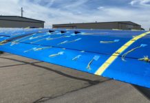
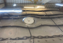
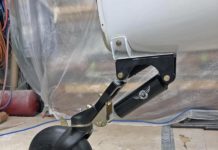
 Aileron cove rib: We found that when installing the left wing aileron cove the lower wing skin is about 3/8″ too short to give edge distance to rivet the cove. We removed about the last inch of the cove rib to allow the cove skins to fit.
–Jim Siebel
Installing cove skins: Why not install small nutplates on the cove ribs? Sure would make inspections and other potential maintenance much easer.
–Jim Rose
Setting flap cove ribs: When setting up the flap cove ribs, check for proper alignment by visualizing or stretching a string across the aft end of the cove ribs for straightness, which can be adjusted slightly to assure a straight trailing edge.
–Dan – GlaStar Component Services
Trailing edge of upper wing skin bonding: The completed aircraft that I have seen so far had wavy trailing edge wing skin, cove skin junction with the exception of Daetweiler’s aircraft. In order to facilitate or more aesthetic finish we opted to bond in place the cove skins with DP 190. Also if you follow the procedure in the manual, you will end up with the rivet shop heads protruding high into the air above the skins. The procedure that we did is as follows.
- Achieving a relaxed bend in the cove skins is extremely important. If you force the cove skins in position they will push the upper skins out of alignment. Also some minor trimming on the flap/cove ribs is necessary for the cove skins to lay flat and fare.
- Dimpled the cove skins at the junction of cove skin/ upper skin. We counter sunk the filler strips which go between the cove skin and the upper wing skin.
- We bonded the cove skin in place using large straight edges top and bottom to clamp the mating surfaces together until the DP 190 had reached a green cure (still not completely hard). At this time we cleaned up the excess and the dimples.
- After clean up and complete cure of DP 190 we used AN 470 head rivets with the heads on the wing skin and the tails being squeezed down into the dimples in the cove skin
The resulting trailing edge after completing this process was as straight as straight gets with no variation.
–Danny – GlaStar Component Services
Cove skin installation: Just started fitting cove skins and have a few thoughts for those following.
1. Drilling the skin holes in the aileron hinge brackets. Can’t see anywhere where this is discussed in the manual.The brackets are made AFTER the skins are drilled and fitted and I can’t find where one is reminded to drill and deburr the skin holes. Doing this, as I did, after riveting the skin on makes deburring difficult, so I suggest that a step 76a, Section X (p 157) be added doing the same step but for the aileron hinge brackets, be considered.at that point.
2. Fitting the aileron cove skin completely overlooks the need for a slot or hole for the aileron push rod (see Figure 86, Section X p 165). Because fitting the ailerons to check for full and free travel is a real fiddle, and without precise detail, that is what is really required, for what it is worth, I cut a hole 1-1/4 wide, spanwise, and within 1 inch of the cove rib immediately outboard of the appropriate hinge bracket, starting in line with the upper of the two tabs. Not tested yet to ensure full and free travel. Alternatively a full spanwise slot to within 1 inch of the cove rib could be left open.
3. Step 84, Sec X p 170. I found the actual depth available for me to fit the cove skin against the lower skin was 1/2 inch max, resulting in the 3/8 centre for the holes, forward of the trailing edge, being very close to the radius of the bend in the skin – hard squeezing and hard to drill without damaging the cove skin. Unfortunately, I drilled the long one first, so I will have to drill the rest likewise to look right. However, I suggest the 3/8 measurement should be revised – more like 1/4. Better still, measure the depth first, then halve this distance, less a little for the curve would be better.
–Peter Washbourn, Kit 5437


