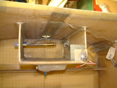
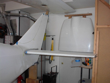
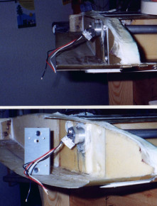
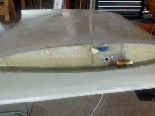
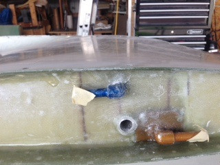
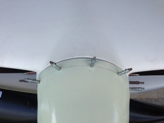
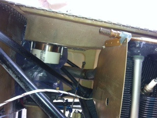
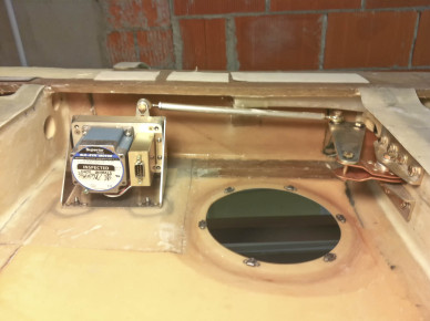
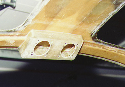
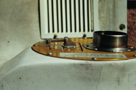
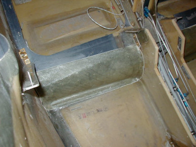
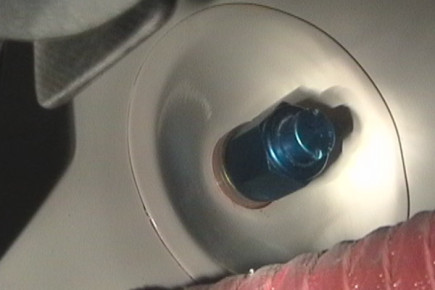
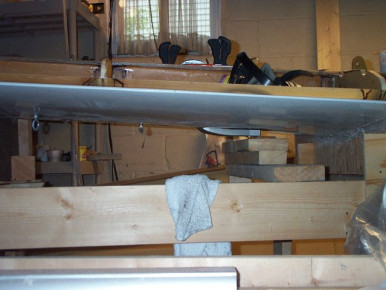
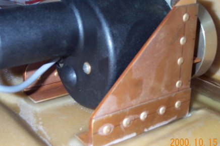
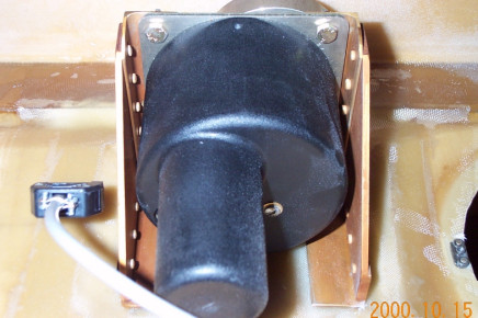
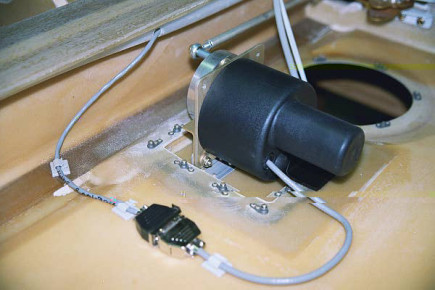
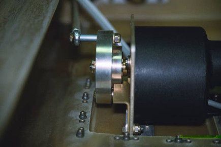
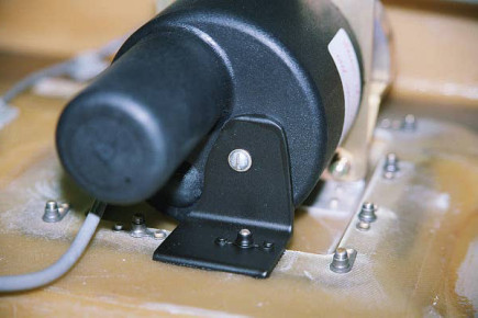
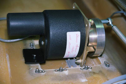
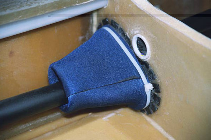
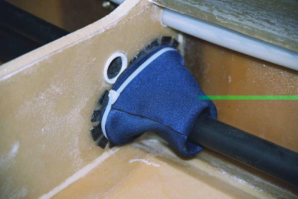
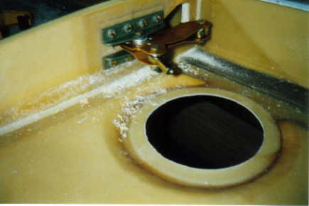
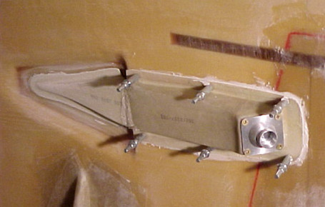
Header Tank Fuel Probe
Header Tank with Vision Fuel Probe Installed - Glasair, Fuel
Bonded in fuel cap flange in left wing. Cut relief in upper skin for landing gear actuator cylinder. Note: The gear actuator clears the skin but not by much so I decided to relieve this area locally to insure that there would never be any interference in this area.
Bonded in fuel cap flange in left wing. Cut relief in upper skin for landing gear actuator cylinder. Note: The gear actuator clears the skin but not by much so I decided to relieve this area locally to insure that there would never be any interference in this area. - Fuel, Glasair, Glasair Super II-s, Wing
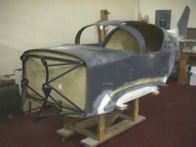
from today's work.
from today's work. - Glasair, Glasair Super II-s, Wing
Laminated shearweb to left rudder half.
Laminated shearweb to left rudder half. - Glasair, Glasair Super II-s, Rudder
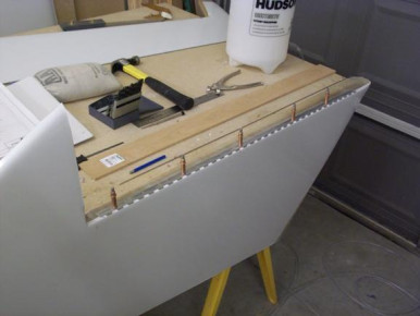
Worked on the rudder hinge today. This photo was taken while attaching the rudder hinge to the right side of the vertical fin.
Worked on the rudder hinge today. This photo was taken while attaching the rudder hinge to the right side of the vertical fin. - Glasair, Glasair Super II-s, Rudder
I just finished drilling all of the holes in the right side of the vertical fin and positioned the hinge in place with clecos.
I just finished drilling all of the holes in the right side of the vertical fin and positioned the hinge in place with clecos. - Glasair, Glasair Super II-s, Rudder
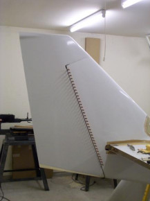
just checking the fit of the rudder.
just checking the fit of the rudder. - Glasair, Glasair Super II-s, Rudder
Worked on attaching the hinge to the rudder shearweb.
Worked on attaching the hinge to the rudder shearweb. - Glasair, Glasair Super II-s, Rudder
Riveted the hinge to the vertical fin and the rudder shearweb. This photo was taken after I finished all the riveting.
Riveted the hinge to the vertical fin and the rudder shearweb. This photo was taken after I finished all the riveting. - Glasair, Glasair Super II-s, Rudder
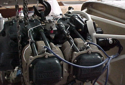
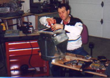
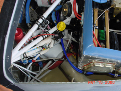
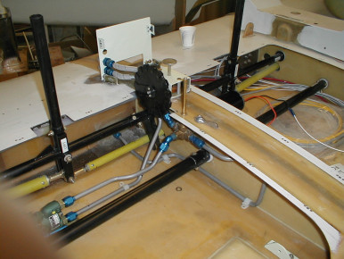
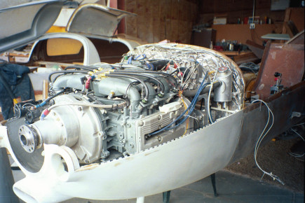
Moved the injector assembly to the left side of the engine from the right side. Added preservative oil to the cylinders and installed desiccant plugs in place of the spark plugs.
Moved the injector assembly to the left side of the engine from the right side. Added preservative oil to the cylinders and installed desiccant plugs in place of the spark plugs. - Engine, Glasair, Glasair Super II-s
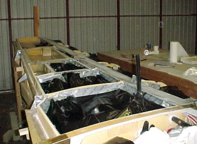
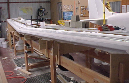
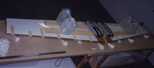
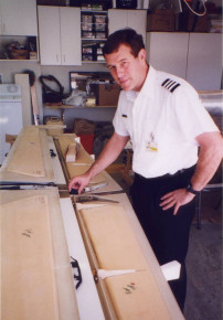
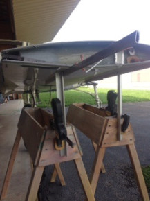
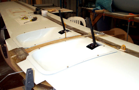
Got wing all ready for closing. Will be closed tomorrow night.
Got wing all ready for closing. Will be closed tomorrow night. - Glasair, Glasair Super II-s, Wing
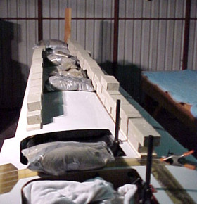
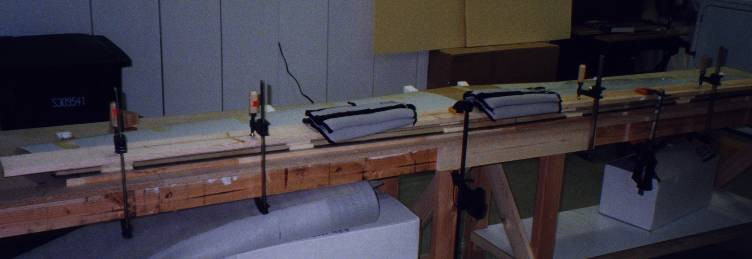
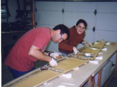
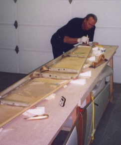
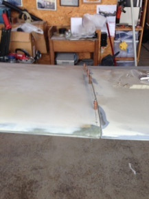
Closed the left wing tonight. Spent about an hour on last minute prep work and then closed it in about 20 minutes with 3 people total.
Closed the left wing tonight. Spent about an hour on last minute prep work and then closed it in about 20 minutes with 3 people total. - Glasair, Glasair Super II-s, Wing
Laminated center seam and added the unidirectional cloth above the aft spar. Filled a few voids between the main spar and the upper skin by drilling holes in the upper skin and injecting resin in the voids.
Laminated center seam and added the unidirectional cloth above the aft spar. Filled a few voids between the main spar and the upper skin by drilling holes in the upper skin and injecting resin in the voids. - Glasair, Glasair Super II-s, Wing
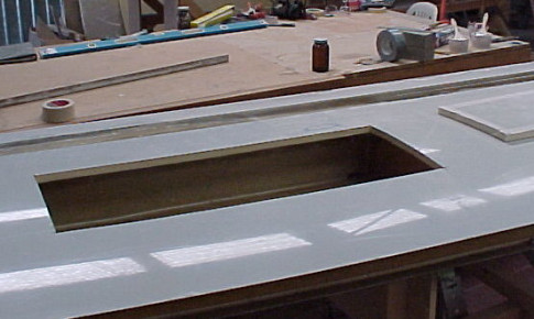
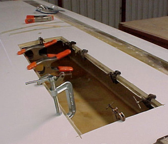
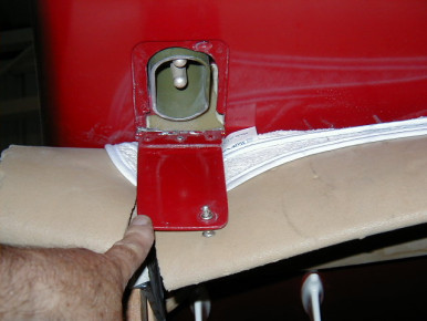
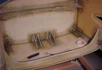
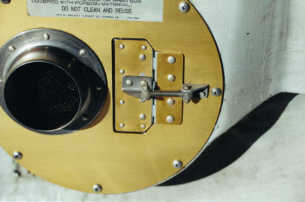
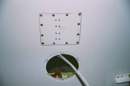
Installed the fuel bay access cover.
Installed the fuel bay access cover. - Fuel, Glasair, Glasair Super II-s, Wing
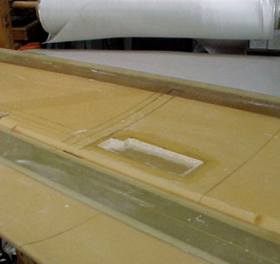
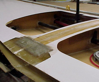
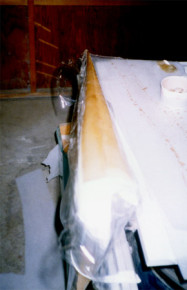
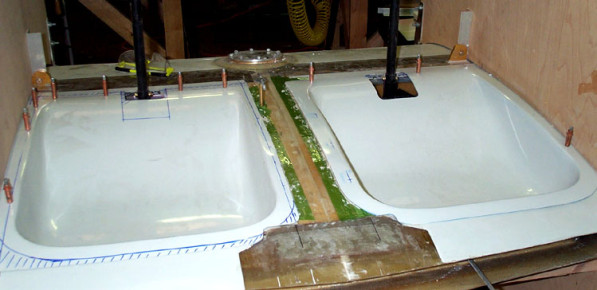
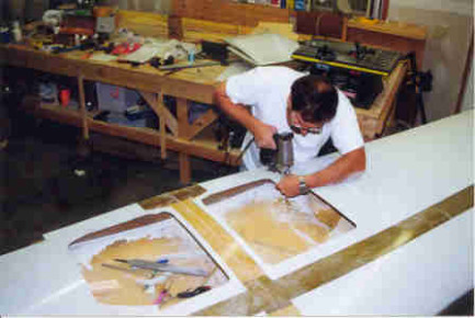
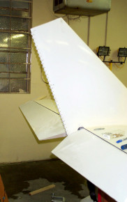
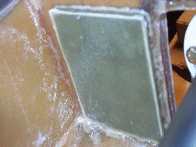
Here's something nobody wants to see, my wing with a big hole in it after closing. As it turns out there was a pretty severe dip in the flange that runs along the forward wall of the fuel cell. This caused a large gap between the tank flange and the upper wing skin. See the other photo for today to see a close-up of the gap. What I did - Cut a hole in the wing skin, injected Resin/Qcell in the gap and then laminated some fiberglass in the area of the flange/wing skin joint.
Here's something nobody wants to see, my wing with a big hole in it after closing. As it turns out there was a pretty severe dip in the flange that runs along the forward wall of the fuel cell. This caused a large gap between the tank flange and the upper wing skin. See the other photo for today to see a close-up of the gap. What I did - Cut a hole in the wing skin, injected Resin/Qcell in the gap and then laminated some fiberglass in the area of the flange/wing skin joint. - Fuel, Glasair, Glasair Super II-s, Wing
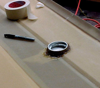
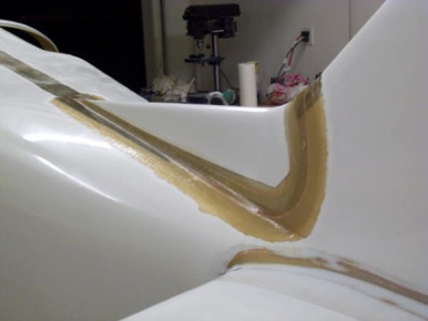
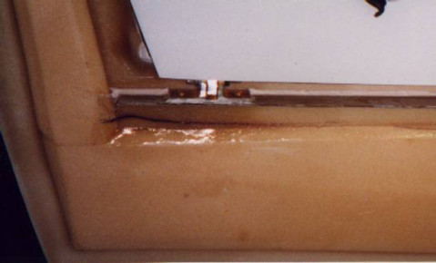
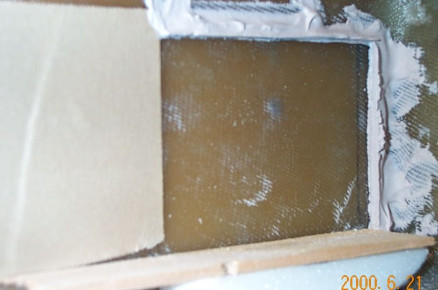
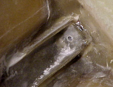
Detail photo showing the gap that caused a massive leak in the aft fuel cell. I have no idea how this happened, but it did.
Detail photo showing the gap that caused a massive leak in the aft fuel cell. I have no idea how this happened, but it did. - Fuel, Glasair, Glasair Super II-s, Wing
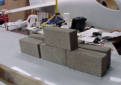
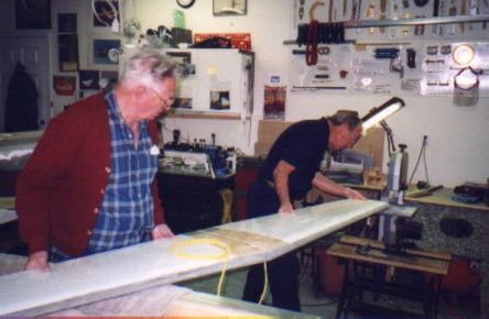
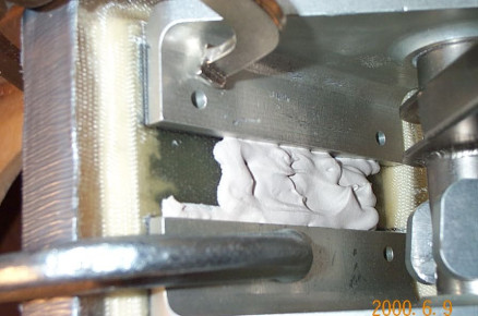
Bonded in flanges to support the portion of the wing I cut out. Will probably bond it back on tomorrow.
Bonded in flanges to support the portion of the wing I cut out. Will probably bond it back on tomorrow. - Glasair, Glasair Super II-s, Wing
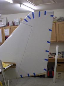
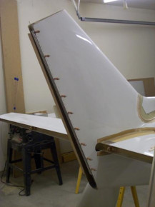
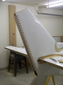
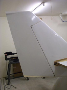
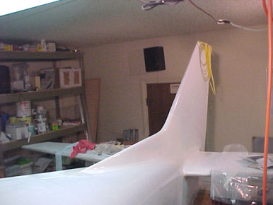
Taped the rudder half's together and fitted it to the vertical fin. I had to do a lot of sanding on the left side of the vertical fin to allow 25 deg. of travel to the left.
Taped the rudder half's together and fitted it to the vertical fin. I had to do a lot of sanding on the left side of the vertical fin to allow 25 deg. of travel to the left. - Glasair, Glasair Super II-s, Rudder
Cut and fit the foam for the rudder actuator rib. Sealed the rib and bonded it in place. Cut the cloth and laminated 4 layers on each side. This photo was taken after I had bonded the rib in place.
Cut and fit the foam for the rudder actuator rib. Sealed the rib and bonded it in place. Cut the cloth and laminated 4 layers on each side. This photo was taken after I had bonded the rib in place. - Glasair, Glasair Super II-s, Rudder
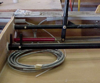
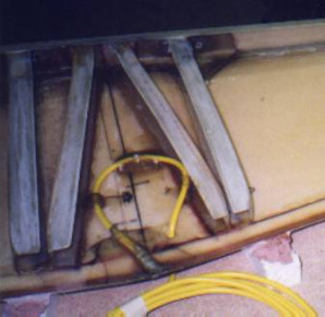
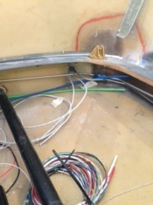
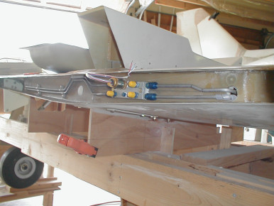
Installed the wire conduit and started installing wires
Installed the wire conduit and started installing wires - Glasair, Glasair Super II-s, Wing
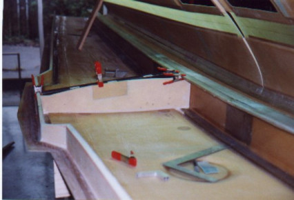
Laminated 4 layers of cloth along the bottom seam. I used my saran wrap method here, after the layers of cloth are on the part I lay a piece of saran wrap (or other thin plastic film) over the lay-up, this way I can work it down and eliminate bubbles by hand while still being able to clearly see the laminate. The saran wrap will be carefully peeled off after the laminate cures.
Laminated 4 layers of cloth along the bottom seam. I used my saran wrap method here, after the layers of cloth are on the part I lay a piece of saran wrap (or other thin plastic film) over the lay-up, this way I can work it down and eliminate bubbles by hand while still being able to clearly see the laminate. The saran wrap will be carefully peeled off after the laminate cures. - Glasair Super II-s, Rudder, Glasair
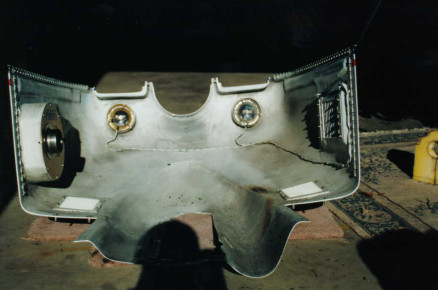
Closed up the aft fuel cell.
Closed up the aft fuel cell. - Glasair Super II-s, Wing, Fuel, Glasair
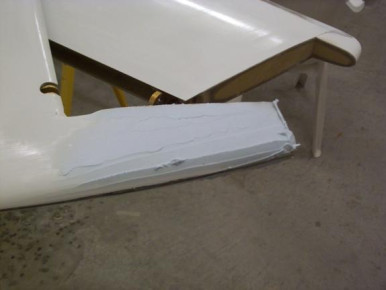
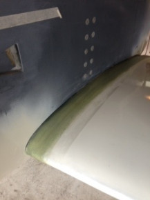
Added another layer to the leading edge. Wanted to add all the layers today but it was too hot, will wait for a cooler day.
Added another layer to the leading edge. Wanted to add all the layers today but it was too hot, will wait for a cooler day. - Glasair Super II-s, Wing, Glasair
Filled and sanded on the horizontal stabilizer and elevators. This photo shows filler applied to the elevator counterweight arm.
Filled and sanded on the horizontal stabilizer and elevators. This photo shows filler applied to the elevator counterweight arm. - Glasair Super II-s, Elevator, Horizontal Stabilizer, Glasair
Cut and sealed the rudder ribs and started fitting them in the rudder. Cut the cloth and laminated 3 layers for the rudder shearweb extension. This photo was taken just before I started fitting the rudder ribs.
Cut and sealed the rudder ribs and started fitting them in the rudder. Cut the cloth and laminated 3 layers for the rudder shearweb extension. This photo was taken just before I started fitting the rudder ribs. - Glasair Super II-s, Rudder, Glasair
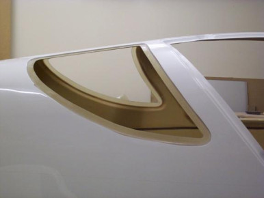
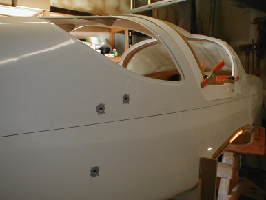
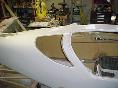
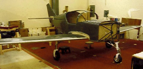
Cutout and sanded the rear windows.
Cutout and sanded the rear windows. - Glasair Super II-s, Window, Glasair
gl-909
Glasair Super II-s, Elevator, Horizontal Stabilizer, Glasair
still filling and sanding in this area.
still filling and sanding in this area. - Glasair Super II-s, Glasair
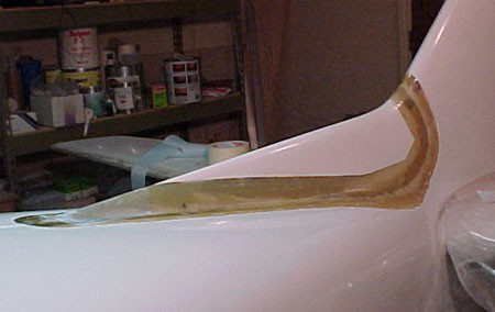
Cut the cloth and laminated 2 layer around the dorsal fin. This photo was taken just after I finished.
Cut the cloth and laminated 2 layer around the dorsal fin. This photo was taken just after I finished. - Glasair Super II-s, Fuselage, Glasair
gl-914
Glasair Super II-s, Rudder, Glasair
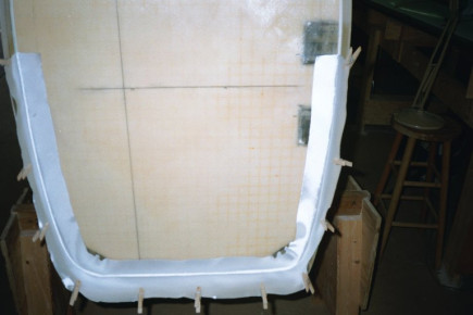
Finished building and bonding the trim tab in place. I had to trial fitting the rudder to the vertical fin six or seven times before I was happy with the fit. Closed the rudder. This photo was taken just after closing.
Finished building and bonding the trim tab in place. I had to trial fitting the rudder to the vertical fin six or seven times before I was happy with the fit. Closed the rudder. This photo was taken just after closing. - Glasair Super II-s, Rudder, Trim, Glasair
Another photo
Another photo - Glasair Super II-s, Rudder, Glasair
Prepped cut outs and jigged horizontal stabilizer for bonding into fuselage.
Prepped cut outs and jigged horizontal stabilizer for bonding into fuselage. - Glasair I, Fuselage, Horizontal Stabilizer, Glasair
Bonded first four laminates into horizontal and fuselage mounting.
Bonded first four laminates into horizontal and fuselage mounting. - Glasair I, Fuselage, Horizontal Stabilizer, Glasair
Built bracing and hung wing from ceiling in garage until needed for mounting to fuselage.
Built bracing and hung wing from ceiling in garage until needed for mounting to fuselage. - Glasair I, Wing, Fuselage, Glasair
Received the vertical fin / rudder extension form Phoenix Composites.
Received the vertical fin / rudder extension form Phoenix Composites. - Glasair Super II-s, Rudder, Glasair
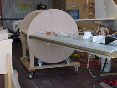
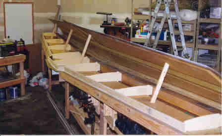
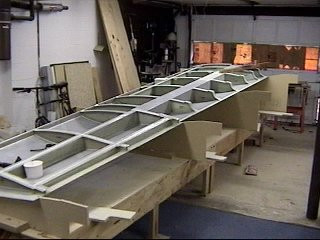
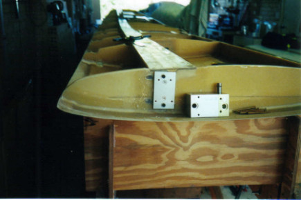
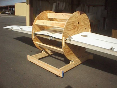
Moved the wing from the wing jig to the rotation jig.
Moved the wing from the wing jig to the rotation jig. - Glasair Super II-s, Wing, Glasair
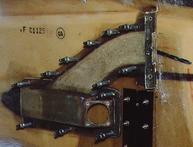
Started fabricating the fuselage portion of the engine mount. Don't look too close to the welds. I'm no expert, but, at least I know I'm getting good penetration.
Started fabricating the fuselage portion of the engine mount. Don't look too close to the welds. I'm no expert, but, at least I know I'm getting good penetration. - Glasair I, Engine, Fuselage, Glasair
Worked on feathering in the wing tank patch area.
Worked on feathering in the wing tank patch area. - Glasair Super II-s, Wing, Glasair
Bonded in and laminated the foam wedges that go in the corner where the aft shearweb and the B ribs meet. This wing rotation jig sure makes this easy.
Bonded in and laminated the foam wedges that go in the corner where the aft shearweb and the B ribs meet. This wing rotation jig sure makes this easy. - Glasair Super II-s, Wing, Glasair
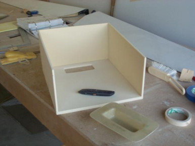
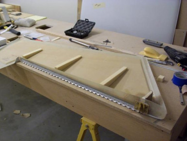
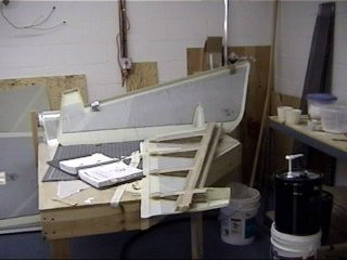
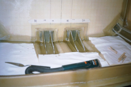
Started cutting and fitting the foam for the header tank.
Started cutting and fitting the foam for the header tank. - Glasair Super II-s, Fuel, Glasair
gl-942
Wing, Glasair
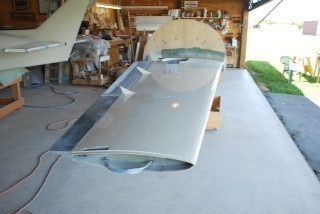
More laminating, the seatpan area and the wing tip area.
More laminating, the seatpan area and the wing tip area. - Glasair Super II-s, Wing, Glasair
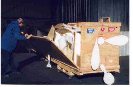
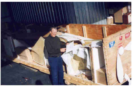
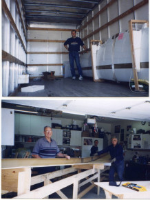
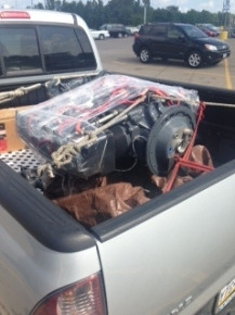
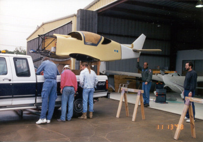
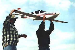
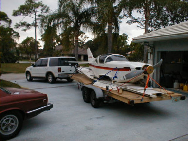
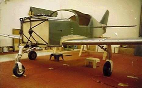
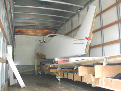
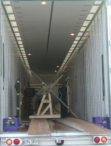
Kit arrives at Nut Tree Airport in Vacaville, CA. Dad commadeers fork lift and driver from Col. Duncan to help unload the 4'X 5' X 24' crate.
Kit arrives at Nut Tree Airport in Vacaville, CA. Dad commadeers fork lift and driver from Col. Duncan to help unload the 4'X 5' X 24' crate. - Glasair Super II-s, Moving, Glasair
It took many people all of December to inventory the entire package. Shortages were sent to Stoddard-Hamilton. Delivery was promissed in January 1999. Wrong extended wing tips (GIII) will be sent back after coordinating with S&H.
It took many people all of December to inventory the entire package. Shortages were sent to Stoddard-Hamilton. Delivery was promissed in January 1999. Wrong extended wing tips (GIII) will be sent back after coordinating with S&H. - Glasair Super II-s, Wing, Glasair
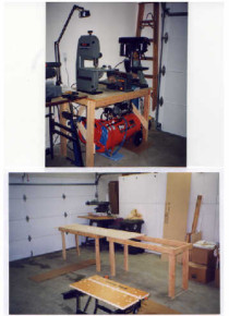
Builders manuals were received in October 1998. We began work on horizontal stabilizer jig. Radial saw was nice, but the compound mitre saw, compressor and nailgun earned a permanent place in our heart on first day. Real time savers!
Builders manuals were received in October 1998. We began work on horizontal stabilizer jig. Radial saw was nice, but the compound mitre saw, compressor and nailgun earned a permanent place in our heart on first day. Real time savers! - Glasair Super II-s, Horizontal Stabilizer, Glasair
Applied first light coat of primer to rudder top and bottom seams. Laminated in bulkhead for counterweight area. Installed wires and plugs for taillight.
Applied first light coat of primer to rudder top and bottom seams. Laminated in bulkhead for counterweight area. Installed wires and plugs for taillight. - Glasair Super II-s, Rudder, Glasair
Manufactured horizontal stabilizer tips. The molded stabilizer tips had to be split with a saw and laminated closed on the ends to get the correct shape (see tape holding shape while curing). Then a two layer laminate (see clamp) was bonded to the inside of the end of the horizontal stabilizer to give a stable surface to hold the tip for additional inside laminates. Stabilizer tips were laminated to horizontal stabilizer. Elevator counterweight arms were laminated on the inside. These are very difficult laminates. The opening is very tight and the glass wants to stick to everything. Finally applied pre-preg layers to a folded piece of thin cardboard. Then slipped the cardboard in the small opening and used a skinny stick to hold the laminates in place while I pulled the card board out. Then used a small brush on a stick to finish the job. Make sure you sand the inside BEFORE you close the elevator. (See inside of tip in picture 4/28/99)
Manufactured horizontal stabilizer tips. The molded stabilizer tips had to be split with a saw and laminated closed on the ends to get the correct shape (see tape holding shape while curing). Then a two layer laminate (see clamp) was bonded to the inside of the end of the horizontal stabilizer to give a stable surface to hold the tip for additional inside laminates. Stabilizer tips were laminated to horizontal stabilizer. Elevator counterweight arms were laminated on the inside. These are very difficult laminates. The opening is very tight and the glass wants to stick to everything. Finally applied pre-preg layers to a folded piece of thin cardboard. Then slipped the cardboard in the small opening and used a skinny stick to hold the laminates in place while I pulled the card board out. Then used a small brush on a stick to finish the job. Make sure you sand the inside BEFORE you close the elevator. (See inside of tip in picture 4/28/99) - Glasair Super II-s, Elevator, Horizontal Stabilizer, Controls, Glasair
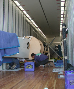
Took horizontal stabilizer to hangar and moved the wing from the hangar to the garage. Original packing was used to secure wing in moving van.
Took horizontal stabilizer to hangar and moved the wing from the hangar to the garage. Original packing was used to secure wing in moving van. - Glasair Super II-s, Wing, Glasair
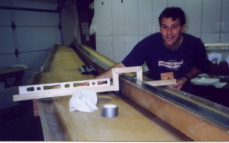
Leveled wing in jig using custom level with a notch for the main spar. Wooden blocks for actual chord line on trailing edge are not shown but must be used as per the builders manual.
Leveled wing in jig using custom level with a notch for the main spar. Wooden blocks for actual chord line on trailing edge are not shown but must be used as per the builders manual. - Glasair Super II-s, Wing, Glasair
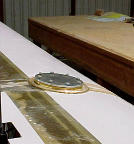
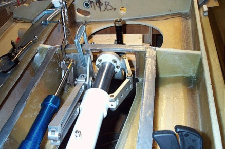
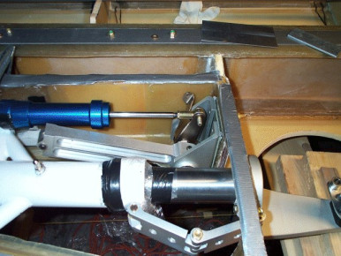
Recessed mounting plate for Fuel Vent Float Valve in right I rib. The wing is thinner at this forward location and the FVFV interferes with the wing joggle if not recessed. 2 layers of BID were added prior to mounting to provide an attach point for the upper wing near the FVFV. (this is an alternate mounting location since we mounted the Vision probe aft to remain clear of fuel caps)
Recessed mounting plate for Fuel Vent Float Valve in right I rib. The wing is thinner at this forward location and the FVFV interferes with the wing joggle if not recessed. 2 layers of BID were added prior to mounting to provide an attach point for the upper wing near the FVFV. (this is an alternate mounting location since we mounted the Vision probe aft to remain clear of fuel caps) - Glasair Super II-s, Wing, Fuel, Glasair
First laminates of entire project are laid in the horizontal stabilizer upper surface. Worried about the humidity a little since it is 65%. Clamped horizontal stabilizer shear web in position in preparation for leveling horizontal stabilizer and bonding shear web in.
First laminates of entire project are laid in the horizontal stabilizer upper surface. Worried about the humidity a little since it is 65%. Clamped horizontal stabilizer shear web in position in preparation for leveling horizontal stabilizer and bonding shear web in. - Glasair Super II-s, Glasair
Last 4 days work: Leveled the horizontal stabilizer in the jig. Had to knock off some of the leading edge shims in order to make the horizontal stabilizer chord line level. Don't bondo any shims in place until you have the upper horizontal stabilizer surface chord line accurate on the jig. Bonded shear web in place.
Last 4 days work: Leveled the horizontal stabilizer in the jig. Had to knock off some of the leading edge shims in order to make the horizontal stabilizer chord line level. Don't bondo any shims in place until you have the upper horizontal stabilizer surface chord line accurate on the jig. Bonded shear web in place. - Glasair Super II-s, Horizontal Stabilizer, Glasair
Bonded B & C ribs in horizontal stabilizer. Filled in a 3 small areas under shear web that were lacking mill fiber.
Bonded B & C ribs in horizontal stabilizer. Filled in a 3 small areas under shear web that were lacking mill fiber. - Glasair Super II-s, Horizontal Stabilizer, Glasair
Laminated B & C ribs to aft shear web. It is amazing how the fabric will change shape and conform to the corner surface.
Laminated B & C ribs to aft shear web. It is amazing how the fabric will change shape and conform to the corner surface. - Glasair Super II-s, Glasair
Fabricated, Q-celled and laminated the C ribs into the horizontal stabilizer. Purchased steel 2 X 4 to use as Straight edge for installing elevator hinges.
Fabricated, Q-celled and laminated the C ribs into the horizontal stabilizer. Purchased steel 2 X 4 to use as Straight edge for installing elevator hinges. - Glasair Super II-s, Elevator, Horizontal Stabilizer, Glasair
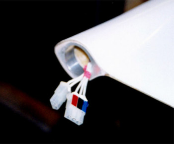
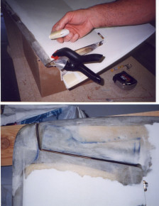
Secured the coaxial cable at the minimum radius specified and siliconed (yikes...don't get it on anything else) the cable exit in the upper skin of the horizontal stabilizer.
Secured the coaxial cable at the minimum radius specified and siliconed (yikes...don't get it on anything else) the cable exit in the upper skin of the horizontal stabilizer. - Glasair Super II-s, Horizontal Stabilizer, Glasair
Made jig to hold horizontal stabilizer verticle. Filled hinge holes with clay, Q-cell radiused the shear web and applied 2 layer laminates to upper and lower horizontal stabilizer panels and shear web. Cut 14 strips of BID for application to the leading edge of the horizontal stabilizer. Repaired bubble in rear shear laminate (photo)
Made jig to hold horizontal stabilizer verticle. Filled hinge holes with clay, Q-cell radiused the shear web and applied 2 layer laminates to upper and lower horizontal stabilizer panels and shear web. Cut 14 strips of BID for application to the leading edge of the horizontal stabilizer. Repaired bubble in rear shear laminate (photo) - Glasair Super II-s, Horizontal Stabilizer, Glasair
Cut out the landing gear holes in the wing. Used a sabre saw.
Cut out the landing gear holes in the wing. Used a sabre saw. - Glasair Super II-s, Wing, Gear, Glasair
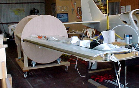
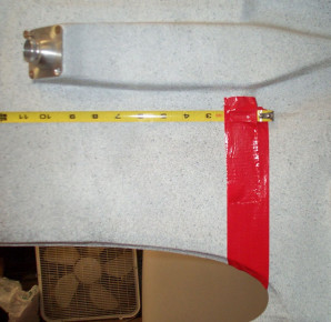
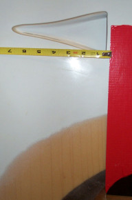
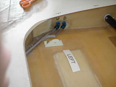
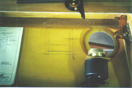
After moving the wing jig so the end lined up with the door to the house (so the fuel probe could be installed thru the door). The jig was re-leveled and the holes for the probe were drilled. The chalk line drawn (actaully snapped) before the fuel baffles were installed was extremely valuable in alignment and drilling of the holes for the probe. Probe extends all the way to the center of the wing (A rib). Unused fuel probe (cut off) is shown near end of probe.
After moving the wing jig so the end lined up with the door to the house (so the fuel probe could be installed thru the door). The jig was re-leveled and the holes for the probe were drilled. The chalk line drawn (actaully snapped) before the fuel baffles were installed was extremely valuable in alignment and drilling of the holes for the probe. Probe extends all the way to the center of the wing (A rib). Unused fuel probe (cut off) is shown near end of probe. - Glasair Super II-s, Wing, Fuel, Glasair
Constructed garage ventilation device from a gable fan and 2 sheet metal flanges bought at Home Depot. After riveting and cutting metal for 2 days I know what the RV guys are going through. It connects to the 6 X 12 garage vent on the wall near the ceiling and forces air out of the garage. We open the door to the house, turn on the fan and the smell goes out and the cool (or warm) house air comes in. It keeps the smell out of the house. Actually the smell is not bad at all. Much better than epoxy!
Constructed garage ventilation device from a gable fan and 2 sheet metal flanges bought at Home Depot. After riveting and cutting metal for 2 days I know what the RV guys are going through. It connects to the 6 X 12 garage vent on the wall near the ceiling and forces air out of the garage. We open the door to the house, turn on the fan and the smell goes out and the cool (or warm) house air comes in. It keeps the smell out of the house. Actually the smell is not bad at all. Much better than epoxy! - Glasair Super II-s, Glasair
Elevator torque tube fasteners were installed. All of the ribs for the elevators were fabricated and installed on upper elevator panel.
Elevator torque tube fasteners were installed. All of the ribs for the elevators were fabricated and installed on upper elevator panel. - Glasair Super II-s, Elevator, Glasair
The elevator spar was Q-celled front and back and a one layer laminate applied to the back of the spar/elevator joint. Notice amount of outboard hinge that needed to be trimmed to allow clearance.
The elevator spar was Q-celled front and back and a one layer laminate applied to the back of the spar/elevator joint. Notice amount of outboard hinge that needed to be trimmed to allow clearance. - Glasair Super II-s, Elevator, Glasair
Sanded trailing edge of horizontal stabilizer to 45 degrees and trimmed ends of horizontal stabilizer in band saw to match the elevator. Redrilled hinge mounting bolts and mounted the hinges.
Sanded trailing edge of horizontal stabilizer to 45 degrees and trimmed ends of horizontal stabilizer in band saw to match the elevator. Redrilled hinge mounting bolts and mounted the hinges. - Glasair Super II-s, Elevator, Horizontal Stabilizer, Glasair
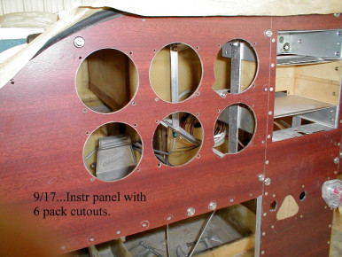
Trimmed engine instrument alum panel to size, drilled mounting holes and installed nutplates in intrument panel.
Trimmed engine instrument alum panel to size, drilled mounting holes and installed nutplates in intrument panel. - Glasair Super II-s, Engine, Panel, Glasair
Laminated the 2 inch strips all around the inside of the gear box area. Yes, this can be done without removing the gear. Also did sanding in other areas in preparation for other 2 inch laminates.
Laminated the 2 inch strips all around the inside of the gear box area. Yes, this can be done without removing the gear. Also did sanding in other areas in preparation for other 2 inch laminates. - Glasair Super II-s, Wing, Gear, Glasair
After discussion on the Glasair News website about jackpad location, the Jackpad/Tie down plates were removed (ooops!) and placed six inches outboard to allow room for the fuel tranfser tunnel. Moving the jackpad location will also make gear door/brake removal/maintenance much easier when the plane is on jacks. Notice the support for the forward fuel bulkhead (optional fuel tank). We plan on slanting the front bulkhead forward to mate with the top wing spar.
After discussion on the Glasair News website about jackpad location, the Jackpad/Tie down plates were removed (ooops!) and placed six inches outboard to allow room for the fuel tranfser tunnel. Moving the jackpad location will also make gear door/brake removal/maintenance much easier when the plane is on jacks. Notice the support for the forward fuel bulkhead (optional fuel tank). We plan on slanting the front bulkhead forward to mate with the top wing spar. - Glasair Super II-s, Wing, Gear, Fuel, Glasair
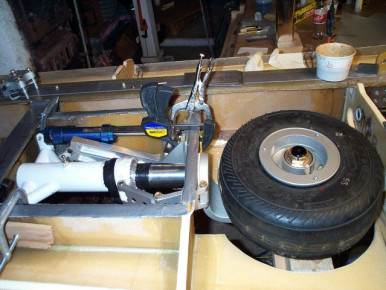
Installed the fuel pickup for the main tank. Notice support for end of the vision fuel probe.
Installed the fuel pickup for the main tank. Notice support for end of the vision fuel probe. - Glasair Super II-s, Wing, Fuel, Glasair
Began to fabricate shims for main gear trunions and gear side braces. Aluminum plates were purchased at the flymart at Air Venture 2000. It takes a lot of time to machine 1/4 aluminim using a drill press, sabre saw and a belt sander!
Began to fabricate shims for main gear trunions and gear side braces. Aluminum plates were purchased at the flymart at Air Venture 2000. It takes a lot of time to machine 1/4 aluminim using a drill press, sabre saw and a belt sander! - Glasair Super II-s, Gear, Glasair
4 days to make sure the elevator counterweights were calculated correctly, manufactured and then installed. Our numbers and figures were double checked by Mr. Airo Gonnella, a retired Boeing engineer. Of course, the final ammount of weight for the internal counterweight arm will be determined after painting.
4 days to make sure the elevator counterweights were calculated correctly, manufactured and then installed. Our numbers and figures were double checked by Mr. Airo Gonnella, a retired Boeing engineer. Of course, the final ammount of weight for the internal counterweight arm will be determined after painting. - Glasair Super II-s, Engine, Elevator, Horizontal Stabilizer, Glasair
All vent and drain holes were drilled in the horizontal stabilizer and elevators. Filling, sanding and laminating of the horizontal stabilizer tips was accomplished to match the elevators. More will be done at later date when were smarted on the exact spacing we want between the elevator and horizontal stabilizer.
All vent and drain holes were drilled in the horizontal stabilizer and elevators. Filling, sanding and laminating of the horizontal stabilizer tips was accomplished to match the elevators. More will be done at later date when were smarted on the exact spacing we want between the elevator and horizontal stabilizer. - Glasair Super II-s, Elevator, Horizontal Stabilizer, Glasair
gn-136
Panel, Glasair
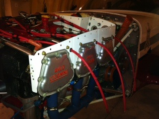
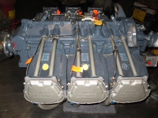
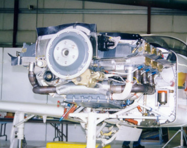
Glasair engines
Plenum cooling - Glasair III, Engine, Glasair
Glasair engine
Io720 - Glasair III, Engine, Glasair
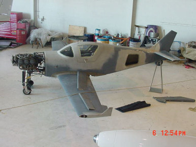
Glasair III
Nice installation - Glasair III, Engine, Glasair
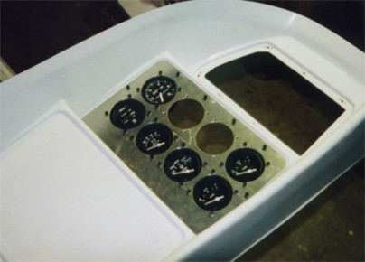
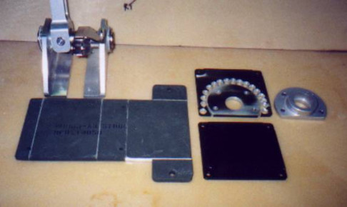
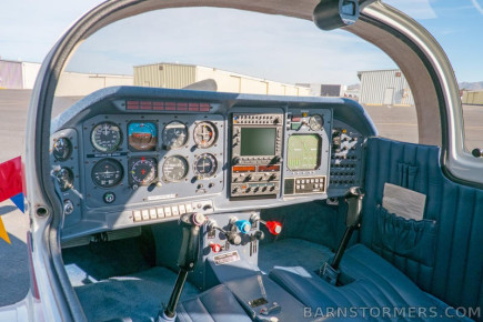
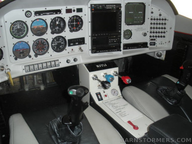
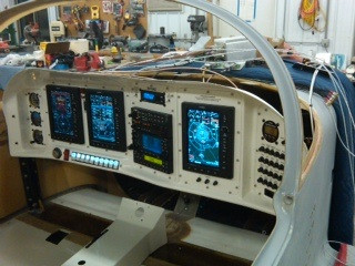
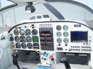
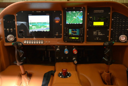
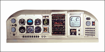
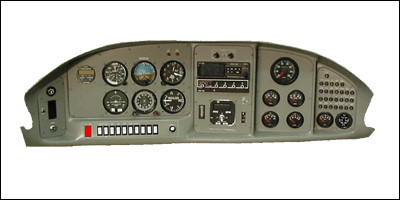
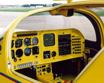
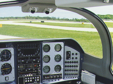
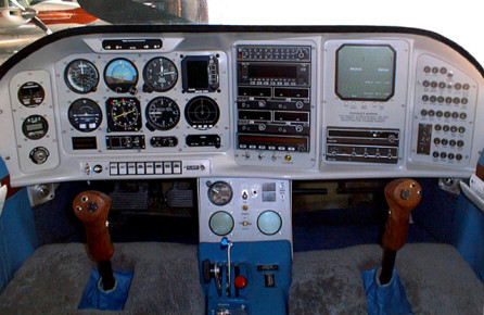
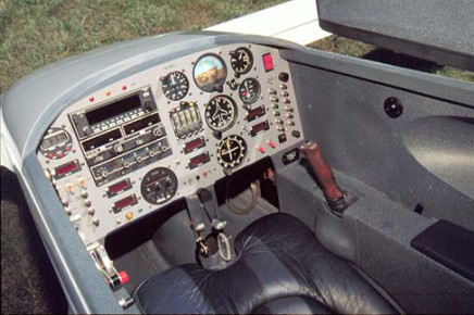
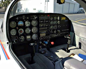
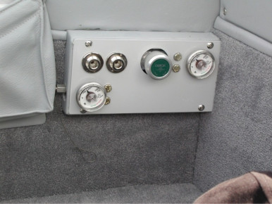
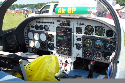
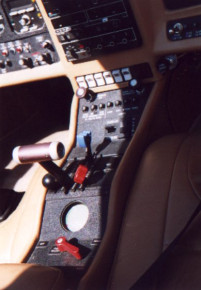
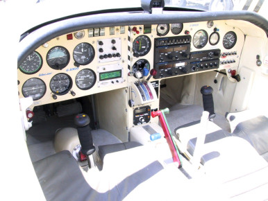
Glasair panel
Panel - Glasair, Panel, Interior
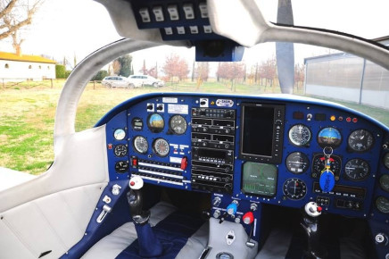
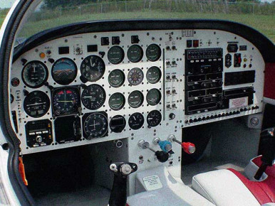
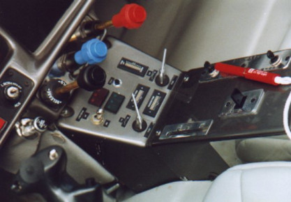
Glasair panel
Glasair - Glasair, Panel, Interior
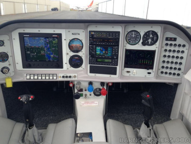
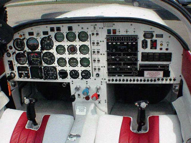
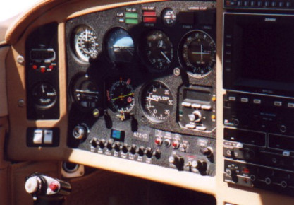
Glasair panel
Glasair - Glasair, Panel, Interior
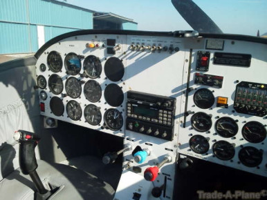
Glasair panel
Glasair - Glasair, Panel, Interior
Glasair panel
Glasair - Glasair, Panel, Interior
Glasair panel
Glasair - Glasair, Panel, Interior
Glasair panel
Glasair - Glasair, Panel, Interior
Glasair panel
Glasair - Glasair, Panel, Interior
Glasair panel
Glasair - Glasair, Panel, Interior
Glasair panel
Glasair - Glasair, Panel, Interior
Glasair panel
Glasair - Glasair, Panel, Interior
Glasair engine
Gladair - Glasair III, Engine, Glasair
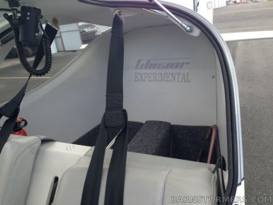
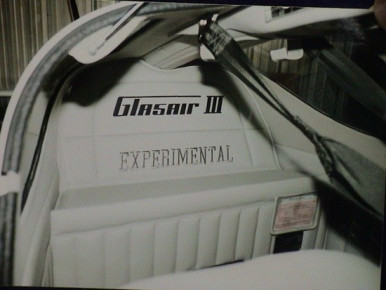
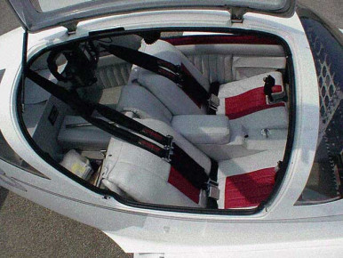
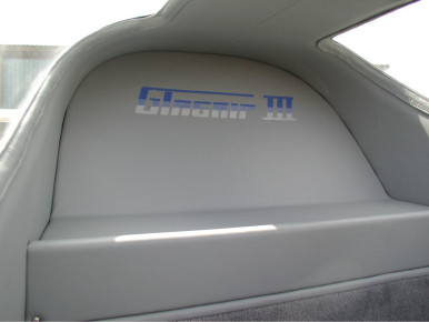
Glasair interior
Glasair - Glasair, Interior, Seat
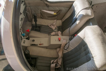
Glasair interior
Glasair - Glasair, Interior
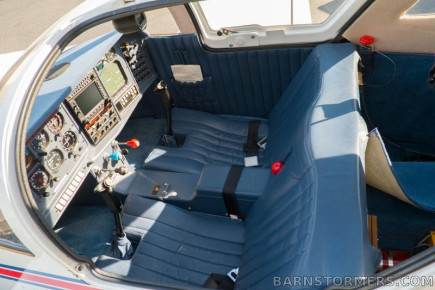
Glasair interior
Glasair - Glasair, Interior, Seat
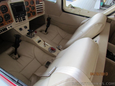
Glasair interior
Glasair - Glasair, Interior, Panel
Glasair interior
Glasair - Glasair, Interior, Panel
Glasair interior
Glasair - Glasair, Interior
Glasair old school panel
Glasair - Glasair, Panel, Interior
Wing tip extensions
Tip before closing - Glasair III, Wing, Glasair
Extensions before closing
Prepping for closing - Glasair III, Wing, Glasair
Tip extension closed
Far from done but closed - Glasair III, Wing, Glasair
Tip extensions with fuel
This shows the fuel fittings as set up for use with fuel float valves - Glasair III, Wing, Fuel, Glasair
Wing extension with fuel
Closed - Glasair III, Wing, Fuel, Glasair
Wing extensions
Plenty of fitting to do, even after following the instructions... - Glasair III, Wing, Glasair
Wing extension jig
Simple jig to fit up wing extensions. Worked well. - Glasair III, Wing, Glasair
gn-316
Glasair III, Wing, Glasair
gn-317
Glasair III, Wing, Glasair
Rotation wing jig
In place for paint on the bottom of the wing - Glasair III, Wing, Paint, Glasair
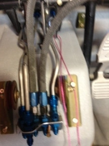
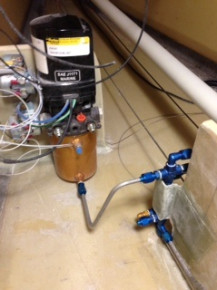
Fuel pump bracket design
In the seat pan area, simple and minimal routing this way. - Glasair III, Wing, Fuel, Glasair
Fuel pump
Pump on the bracket - Glasair III, Wing, Fuel, Glasair

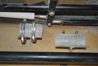
Hydraulics routing
Made a bracket to control the routing go the lines to the nose gear. - Glasair III, Gear, Controls, Glasair
gn-325
Glasair III, Gear, Firewall, Glasair
gn-326
Glasair III, Gear, Glasair
gn-327
Glasair III, Wing, Fuselage, Gear, Glasair
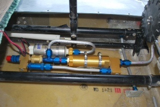
Hydraulic manifold to the nose gear
Manifold with fittings - Glasair III, Gear, Glasair
gn-330
Glasair III, Gear, Horizontal Stabilizer, Glasair
gn-331
Glasair III, Gear, Glasair
gn-332
Glasair III, Gear, Glasair
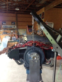
New engine
My engine, gappless rings and dual electronic ignition. Exciting time in the build - Glasair III, Engine, Glasair
gn-334
Glasair III, Gear, Glasair
gn-335
Glasair III, Wing, Gear, Glasair
gn-336
Glasair III, Gear, Glasair
gn-337
Glasair III, Gear, Glasair
gn-338
Glasair III, Gear, Glasair
Hydraulic pump first line bent and run
Hydraulic line to the pump - Glasair III, Gear, Glasair
gn-340
Glasair III, Engine, Glasair
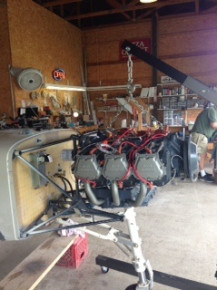
Engine install, glasair III
Going on the airplane for the first time - Glasair III, Engine, Glasair
Engine mounting
Glasair III - Glasair III, Engine, Glasair
Glasair III, main gear
Sitting on the mains. - Glasair III, Gear, Glasair
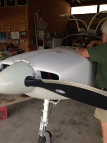
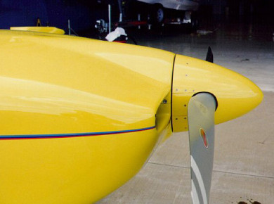
Spinner fit
Extra challenges with the Aerocomposites prop. Spinner fit. - Glasair III, Prop, Glasair
Spinner fit
Spinner fit - Glasair III, Prop, Glasair
Cowl fittup
Fitting cowl - Glasair III, Cowl, Glasair
Cowl hinge pin work
Cowl work - Glasair III, Cowl, Glasair
Engine and cowl
Fun to progress. - Glasair III, Engine, Cowl, Exhaust, Glasair
Working fwf
Fwf - Glasair III, Engine, Glasair
Cowl work glasair III
Glasair - Glasair III, Cowl, Glasair
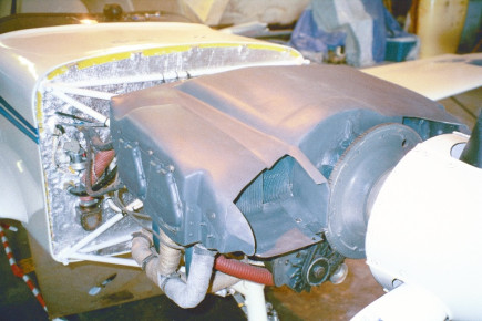
Glasair III induction
Induction on the side of the cowl - Glasair III, Engine, Cowl, Induction, Glasair
Glasair III
Induction - Glasair III, Engine, Induction, Glasair
Glasair III baffling and oil cooler opening
Shows the oil cooler opening. Louvers not yet installed - Glasair III, Engine, Glasair
Glasair III cowl
Inside cowl hinge work - Glasair III, Cowl, Glasair
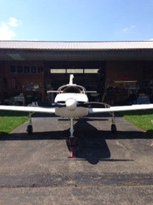
Glasair III
Glasair III first time rolling outside the hangar. - Glasair III, Completed, Glasair
Glasair III
Rolling - Glasair III, Completed, Glasair
Glasair III prop
Aerocomposites prop - Glasair III, Prop, Glasair

Glasair III
What a mess. Gear system wiring just for testing the gear - Glasair III, Gear, Electrical, Glasair
Glasair III panel in process
Lots to do - Glasair III, Panel, Interior, Glasair
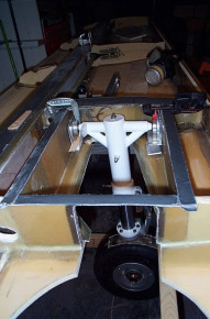
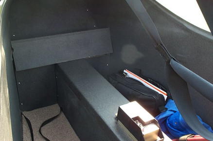
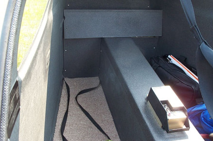
Header tank
Looking forward in the fuselage. - Glasair, Fuselage, Fuel
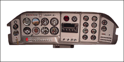
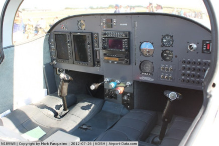
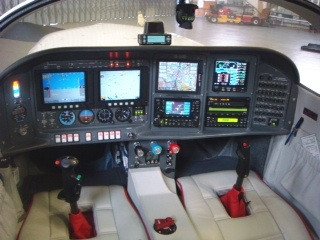
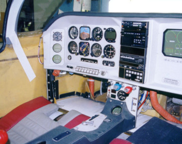
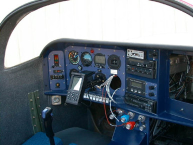
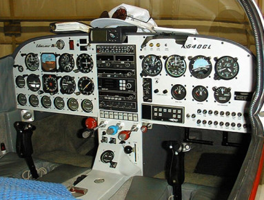
Glasair Super II-FT Panel
N232MD, 2W6 - Glasair Super II, Panel, Interior, Glasair
External battery connectoin
3-pin battery connection on Glasair III - Glasair III, Fuselage, Electrical, Glasair
External battery connector
Inside wiring of connector to external battery connector - Glasair III, Fuselage, Electrical, Glasair
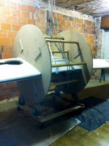
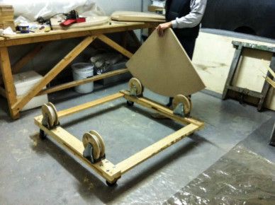
wheel wing jig
my way for wheel wing jig - Glasair III, Wing, Tools, Glasair
wing jig wheel
my wing jig wheel - Glasair III, Wing, Glasair
wing jig wheel
my wing jig wheel - Glasair III, Wing, Glasair
mudguard to the main landing gear
my modification: mudguard to the main landing gear - Glasair III, Gear, Glasair
mudguard to the main landing gear
My mudguard to the main landing gear - Glasair III, Gear, Glasair
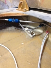
servo - autopilot
installation of Aileron's autopilot servo - Glasair III, Servo, Flaps, Ailerons, Controls, Autopilot, Glasair
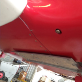
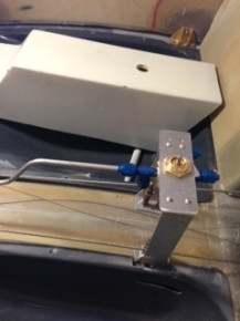
GIII Header tank drain locaton
Header tank drain relocated to the right lower fuselage from the suggested area in the nose wheel well. - Glasair III, Fuselage, Fuel, Glasair
gn-74
Panel, Glasair
gn-76
Panel, Glasair
gn-80
Panel, Glasair
gn-81
Panel, Glasair
ib-111
Firewall, Engine, Glasair
ib-112
Engine, Firewall, Glasair
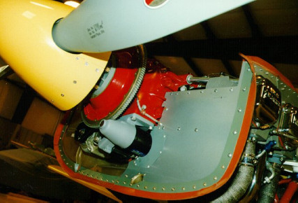
Dennis Heussers N333HK
Dennis S. Heusser's Super II RG N333HK - Engine Detail - Glasair Super II, Engine, Glasair
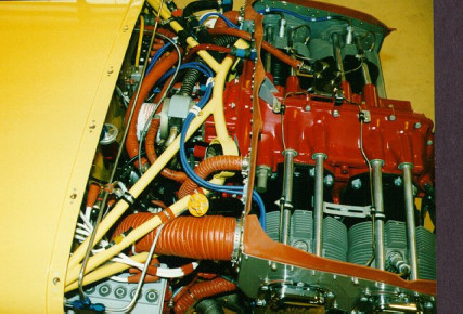
Dennis Heusser's N333HK
Dennis S. Heusser's Super II RG N333HK - Engine Detail - Glasair Super II, Engine, Glasair
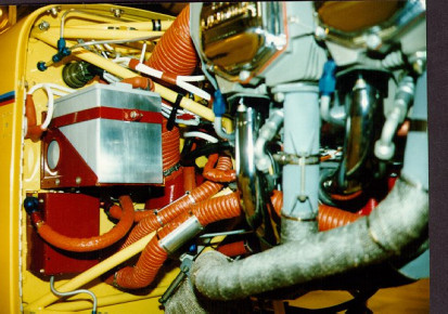
Dennis Heusser's N333HK
Dennis S. Heusser's Super II RG N333HK - Engine Detail - Glasair Super II, Engine, Glasair
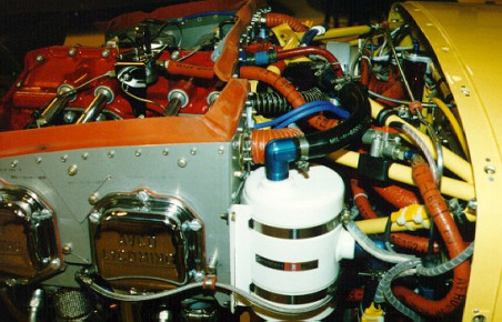
Dennis Heusser's N333HK
Dennis S. Heusser's Super II RG N333HK - Engine Detail - Glasair Super II, Engine, Glasair
Dennis Heusser's N333HK
Dennis S. Heusser's Super II RG N333HK - Front Gear Detail - Glasair Super II, Gear, Cowl, Glasair
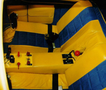
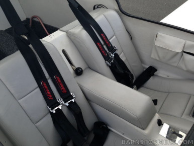
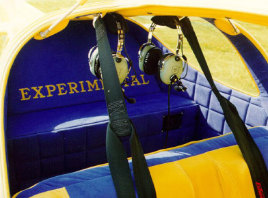
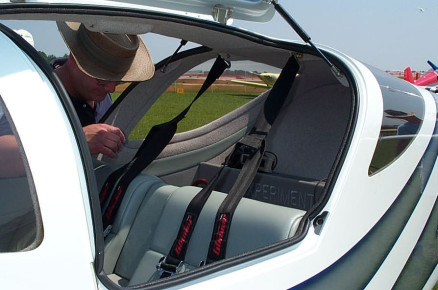
N333HK Seat Detail
Dennis S. Heusser's Super II RG N333HK Seat Detail - Glasair Super II, Interior, Completed, Glasair, Seat
Glasair Super III Prop
New Glasair Super III Prop to replace the old one after bob gavinski's dead stick landing. - Glasair III, Engine, Prop, Glasair
Dennis Heusser's N333HK Rear Seats
Dennis Heusser's Super II RG - Rear Seat Details - Glasair Super II, Interior, Seat, Glasair
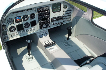
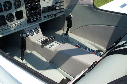
Dennis Heusser's N333HK Panel
Dennis Heusser's Super II RG N333HK - Instrument Panel Details. - Glasair Super II, Panel, Completed, Glasair
Dennis Heusser's N333HK
Dennis Heusser's N333HK - Prop and spinner detail - Glasair Super II, Prop, Glasair
John Krueger's Glasair III
John Krueger's Glasair III nearing completion - Moving the plane. - Glasair III, Fuselage, Moving, Glasair
Cabin Air System on N450WM
Cabin overhead air system on N450WM - Builder: Michael Arbuthnot - Glasair III, Fuselage, Glasair
Cabin Air System on N450WM
Cabin overhead air system on N450WM - Builder: Michael Arbuthnot - Glasair III, Fuselage, Panel, Glasair
Cabin Air System on N450WM
Cabin overhead air system on N450WM - Builder: Michael Arbuthnot - Glasair III, Fuselage, Glasair
Cabin Air System on N450WM
Cabin overhead air system on N450WM - Builder: Michael Arbuthnot - Glasair III, Fuselage, Glasair
Glasair Super III Engine
Glasair Super III Engine after the dead stick landing - Glasair III, Engine, Glasair
Cabin Air System on N450WM
Cabin overhead air system on N450WM - Builder: Michael Arbuthnot - Glasair III, Fuselage, Glasair
Cabin Air System on N450WM
Cabin overhead air system on N450WM - Builder: Michael Arbuthnot - Glasair III, Fuselage, Glasair
Glasair Super III Cockpit
Glasair Super III cockpit photo. Owner Bob Gavinski - Glasair III, Panel, Glasair
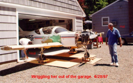
N15F Super II RG
Neal Garvin and Hal Mandly's Super II RG N15F getting ready to run the engine for the first time. - Glasair Super II, Engine, Completed, Moving
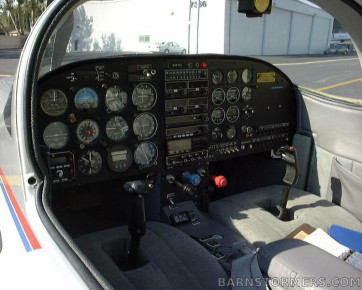
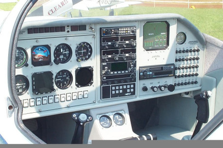
Rob Wyders Glasair IIs RG Panel
Rob Wyders Glasair IIs RG Panel - Glasair Super II, Panel, Glasair
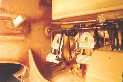
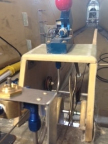
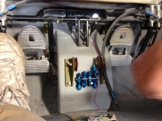
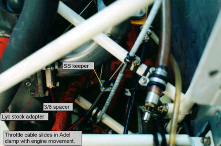
Alteranate Brake Pedal Installation
Here is a picture of an alternate brake pedal installation I did because of an oversize (12 gallon) header tank in my IIS RG. I used existing attatch points for the custom steel pivot arms and was able to mount the brake cylinders on the firewall directly behind the pedals. Builder: Chris Smith - Glasair Super II, Fuel, Controls, Glasair
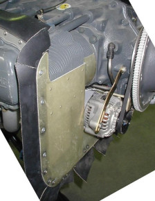
Oil Cooler Installation
Roger Heisdorffer told me that this setup has worked very well for him, now keep in mind that he Has a G I with a IO360 A1A with 10 to 1 pistons, (so he really has about 220HP +or-. And he has lived in AZ where it does get hot. And one more thing, his oil Cooler is a standard GI sized oil cooler. I believe he claims his oil temp never gets Above 190*. Anyway I used this setup with the III oil cooler just to be safe, I figure If a little is good a lot must be better. I purchased my cooler from Chief for $569.00 PN SW10614R (I believe the People at Chief gave me that inf. because other GIII builders were buying oil coolers From them instead of paying Stoddards inflated prices). Builder: Mike James - Glasair Super II, Engine, Cowl, Glasair
Oil Cooler Installation
Roger Heisdorffer told me that this setup has worked very well for him, now keep in mind that he Has a G I with a IO360 A1A with 10 to 1 pistons, (so he really has about 220HP +or-. And he has lived in AZ where it does get hot. And one more thing, his oil Cooler is a standard GI sized oil cooler. I believe he claims his oil temp never gets Above 190*. Anyway I used this setup with the III oil cooler just to be safe, I figure If a little is good a lot must be better. I purchased my cooler from Chief for $569.00 PN SW10614R (I believe the People at Chief gave me that inf. because other GIII builders were buying oil coolers From them instead of paying Stoddards inflated prices). Builder: Mike James - Glasair Super II, Engine, Glasair
ib-1508
Engine, Glasair
ib-1509
Engine, Glasair
Rear fuse ribs A and B
Rear fuse ribs A and B as they are installed at the horizontal stab. Builder: Allen Rockwell - Glasair Super II, Fuselage, Horizontal Stabilizer, Glasair
ib-1510
Engine, Glasair
ib-1511
Engine, Glasair
ib-1512
Engine, Glasair
ib-1513
Engine, Glasair
Look Mom, No Prop
This is a scratch built Glasair III slope soaring glider. Yes, I said glider. Builder: Steve Wilcox - Glasair III, Other, Glasair
Engine mount supports
Installing the engine mount supports to the inside of the firewall. Builder: Allen Rockwell - Glasair Super II, Engine, Fuselage, Glasair
Inside of Glasair II Lower Cowling
Inside of Glasair II Lower Cowling. builder: Neal Garvin - Glasair II, Cowl, Glasair
Glasair III style oil cooler installation
Glasair III style oil cooler installation. Builder: Neal Garvin - Glasair, Cowl
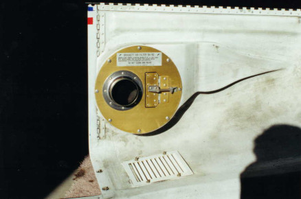
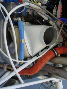
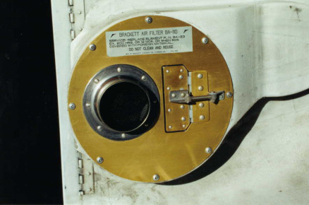
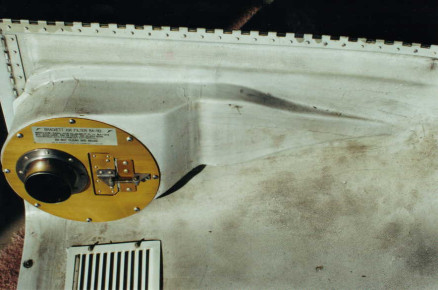
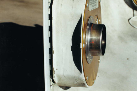
Air induction system detail
Air induction system detail. Builder: Neal Garvin - Glasair, Cowl, Induction
Air induction system detail
Air induction system detail. Builder: Neal Garvin - Glasair, Cowl, Induction
Air induction system detail
Air induction system detail. Builder: Neal Garvin - Glasair, Cowl, Induction
Air induction system detail
Air induction system detail. Builder: Neal Garvin - Glasair, Cowl, Induction
Air induction system detail
Air induction system detail. Builder: Neal Garvin - Glasair, Cowl, Induction
Air induction system detail
Air induction system detail. Builder: Neal Garvin - Glasair, Cowl, Induction
Ribs in the wing
All the ribs installed in the wing of Steve Tehee's Super II - Glasair Super II, Wing, Glasair
Lancair ES Rudder Construction
Lancair ES Rudder Construction - Rudder, Glasair
Lancair ES Rudder Construction
Lancair ES Rudder Construction - Rudder, Glasair
Lancair ES Wing Construction
Lancair ES Wing Construction - Wing, Glasair
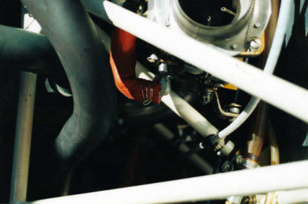
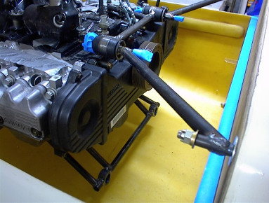
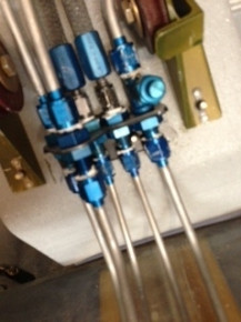
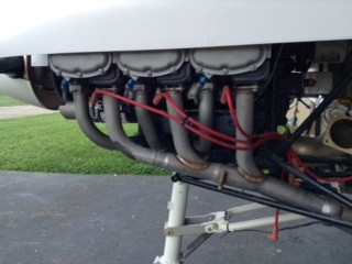
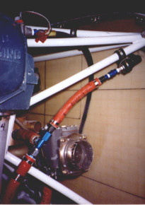
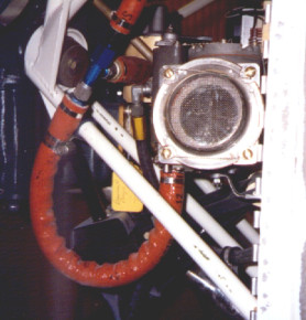
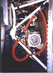
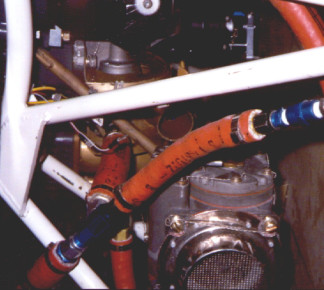
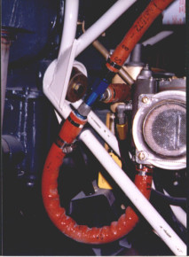
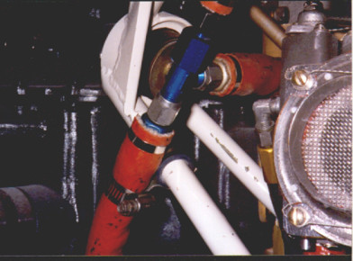
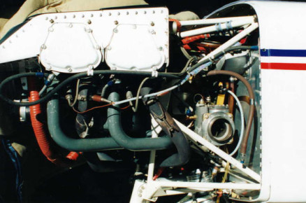
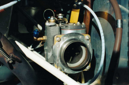
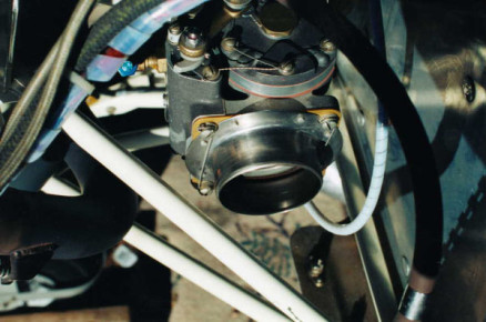
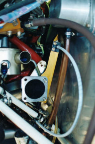
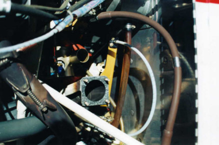
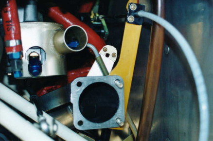
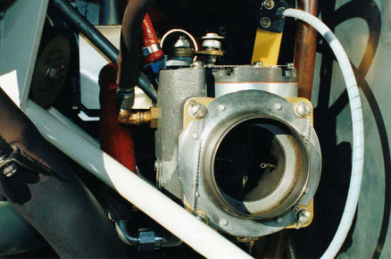
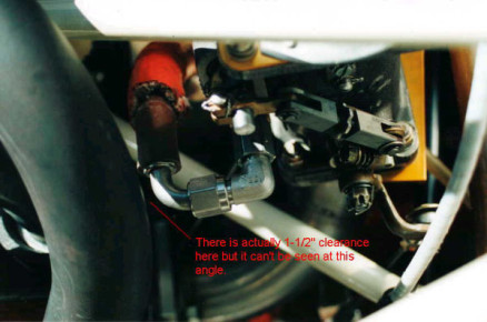
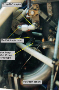
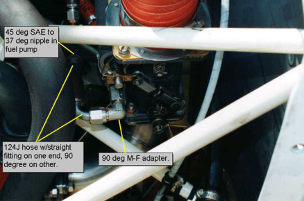
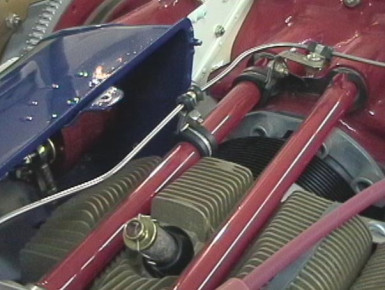
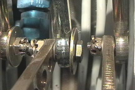
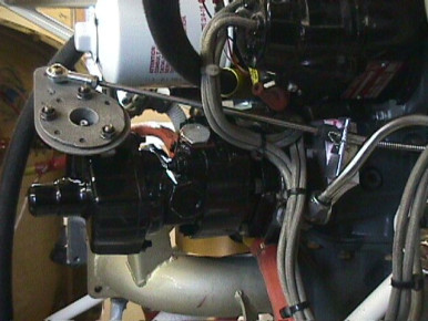
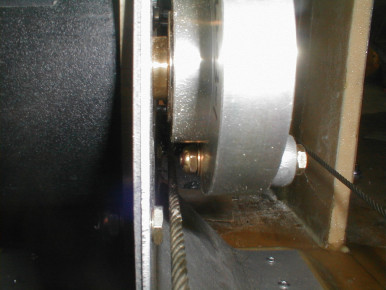
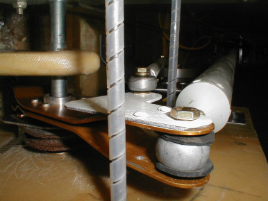
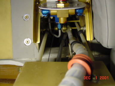
Injector Fuel Servo and Elbow Detail
Injector Fuel Servo and Elbow Detail on Neal Garvin's Glasair II, N15F - Glasair II, Engine, Servo, Fuel, Glasair
Injector Fuel Servo and Elbow Detail
Injector Fuel Servo and Elbow Detail on Neal Garvin's Glasair II, N15F - Glasair II, Engine, Servo, Fuel, Glasair
Injector Fuel Servo and Elbow Detail
Injector Fuel Servo and Elbow Detail on Neal Garvin's Glasair II, N15F - Glasair II, Engine, Servo, Fuel, Exhaust, Glasair
Injector Fuel Servo and Elbow Detail
Injector Fuel Servo and Elbow Detail on Neal Garvin's Glasair II, N15F - Glasair II, Engine, Servo, Fuel, Glasair
Injector Fuel Servo and Elbow Detail
Injector Fuel Servo and Elbow Detail on Neal Garvin's Glasair II, N15F - Glasair II, Engine, Servo, Fuel, Glasair
Working on the B rib
Working on the B Rib in Steve Tehee's Glasair Super II - Glasair Super II, Wing, Glasair
Injector Fuel Servo and Elbow Detail
Injector Fuel Servo and Elbow Detail on Neal Garvin's Glasair II, N15F - Glasair II, Engine, Servo, Fuel, Glasair
Injector Fuel Servo and Elbow Detail
Injector Fuel Servo and Elbow Detail on Neal Garvin's Glasair II, N15F - Glasair II, Engine, Servo, Fuel, Glasair
Injector Fuel Servo and Elbow Detail
Injector Fuel Servo and Elbow Detail on Neal Garvin's Glasair II, N15F - Glasair II, Engine, Servo, Fuel, Glasair
Injector Fuel Servo and Elbow Detail
Injector Fuel Servo and Elbow Detail on Neal Garvin's Glasair II, N15F - Glasair II, Engine, Servo, Fuel, Glasair
Injector Fuel Servo and Elbow Detail
Injector Fuel Servo and Elbow Detail on Neal Garvin's Glasair II, N15F - Glasair II, Engine, Servo, Fuel, Glasair
Injector Fuel Servo and Elbow Detail
Injector Fuel Servo and Elbow Detail on Neal Garvin's Glasair II, N15F - Glasair II, Engine, Servo, Fuel, Glasair
Injector Fuel Servo and Elbow Detail
Injector Fuel Servo and Elbow Detail on Neal Garvin's Glasair II, N15F - Glasair II, Engine, Servo, Fuel, Glasair
NACA Scoop Location and Orientation
NACA Scoop Location and Orientation on a Glasair Super II RG. Builder: Allen Rockwell - Glasair Super II, Fuselage, Glasair
NACA Scoop Location and Orientation
NACA Scoop Location and Orientation on a Glasair Super II RG. Builder: Allen Rockwell - Glasair Super II, Fuselage, Glasair
NACA Scoop Location and Orientation
NACA Scoop Location and Orientation on a Glasair Super II RG. Builder: Allen Rockwell - Glasair Super II, Fuselage, Glasair
Fiberglass roving - B Rib
Working on the B rib fiberglass roving on Steve Tehee's Super II - Glasair Super II, Wing, Glasair
NACA Scoop Location and Orientation
NACA Scoop Location and Orientation on a Glasair Super II RG. Builder: Allen Rockwell - Glasair Super II, Fuselage, Glasair
Installing The Seatpans in a Glasair
Installing The Seatpans in a Glasair Super II RG. Builder: Allen Rockwell - Glasair Super II, Wing, Glasair
Seatpans Installed
Seatpans installed in my Glasair Super II RG. Builder: Allen Rockwell - Glasair Super II, Wing, Glasair
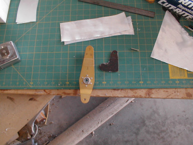
Elevator Hinge Brackets - Alignment
Detail of the alignment process with the bushing, hinge bracket and taut fishing line. - Glasair, Elevator, Horizontal Stabilizer
Installing the seat pans
Installing the seat pans in the wing of Steve Tehee's Super II - Glasair Super II, Wing, Glasair
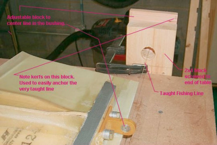
Hinge Bracket Installation - Alignment System
Annotated picture shows the basics of another builder's hint previously submitted by Neal Garvin. It uses the taut fishing line method with bushings in the bracket to align the hinges. - Glasair, Horizontal Stabilizer
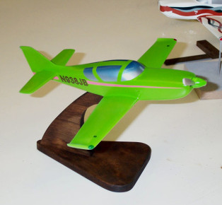
Glasair Desktop Model
Glasair Desktop Model custom built and finished by R&D Technical Services - Glasair, Other
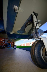
Landing Gear Detail
Landing gear detail on a Glasair Super II RG. Builder: Allen Rockwell - Glasair Super II, Gear, Glasair
Scott Musgrave's Glasair Super II-FT
Scott Musgrave's Glasair Super II-FT Kit number 2353. - Glasair Super II, Fuselage, Glasair
Riveting the Rudder Hinge
Riveting the rudder hinge on a Glasair Super II RG. Builder: Allen Rockwell - Glasair Super II, Rudder, Fuselage, Glasair
GIII Nearing completion
Just hand each visitor a rag and some polish and this is how your pipes end up looking. - Glasair III, Engine, Glasair
Control Tunnel Detail
Control Tunnel Detail on Chris Smith's Glasair IIS RG - Glasair Super II, Fuselage, Controls, Glasair
Fuel Vent Scoop Detail
Fuel vent scoop detail on Chris Smith's Glasair IIS RG - Glasair Super II, Wing, Fuel, Glasair
Rear Spar Closeout Detail
Rear spar closeout detail on Chris Smith's Glasair IIS RG - Glasair Super II, Fuselage, Glasair
Attaching the Aileron Hinges
Attaching the Aileron Hinges to the wing trailing edge and the aileron lower skin. Builder: Allen Rockwell - Glasair, Wing, Ailerons
Attaching the Aileron Hinges
Attaching the Aileron Hinges to the wing trailing edge and the aileron lower skin. Builder: Allen Rockwell - Glasair, Wing, Ailerons
N223B Almost ready to fly.
Bob Buckthal's N223B Almost ready to fly. A preliminary weigh-in indicates that we'll be very close to 1300 pounds at first flight with a constant speed prop and an IO360A1D6. - Glasair Super II, Completed, Panel, Glasair
Fitting the Upper Aileron Skins
Fitting the upper aileron skins on a Glasair Super II RG. Builder: Allen Rockwell - Glasair Super II, Wing, Ailerons, Glasair
Fitting the Upper Aileron Skins
Fitting the upper aileron skins on a Glasair Super II RG. Builder: Allen Rockwell - Glasair Super II, Wing, Ailerons, Glasair
pics
Glasair, Engine
Sample Instrument Panel
Unknown aircraft, unknown builder. - Glasair, Panel
Glasair Interior
Unknown builder. - Glasair, Interior, Seat
Nice Longeze Panel
Unknown Builder. - Glasair, Panel
Glasair Instrument Panel
Unknown builder. - Glasair, Panel
Glasair Flat Instrument Panel
unknown builder. - Glasair, Panel
Glasair Instrument Panel
unknown builder. - Glasair, Panel
Pressurized Glasair III Project
Found picture on web. Unknown builder. - Glasair III, Fuselage, Glasair
Pressurized Glasair III Project
Found Pic on Web. Unknown builder. - Glasair III, Fuselage, Glasair
Pressurized Glasair III Project
Unknown builder. - Glasair III, Engine, Fuselage, Glasair
Glasair I RG Empenage
This Aircraft had Landing incident. - Glasair I, Fuselage, Incident, Glasair
Installation of Forward Ribs
Installation of Forward Ribs in Chris Yeele's Glasair Super II - Glasair Super II, Wing, Glasair
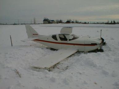
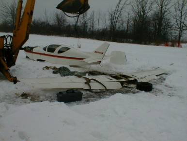
Unfortunate Landing Incident
Gear folded when aircraft departed pavement. - Glasair I, Gear, Completed, Incident
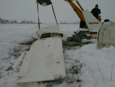
Recovery of Damaged Glasair I RG
Aircraft suffered gear collapse in grass on landing rollout. - Glasair I, Gear, Completed, Incident
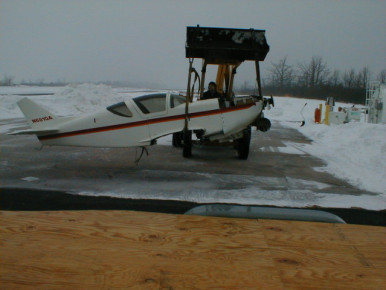
Glasair I RG Wreckage Recovery
Aircraft Damaged in Landing Incident. Demated for transport. - Glasair I, Completed, Incident, Moving
Glasair I RG Fractured Wing Mount
This is the left main wing mount of a crashed Glasair I RG. The wing experienced a significant lateral loading during the crash. Mount sheared at surface of skin. These are the thinner G-I mounts. - Glasair I, Wing, Completed, Incident, Glasair
Glasair I RG Fractured Wing Attachment
Another pic of sheared wing mount. - Glasair I, Wing, Completed, Incident, Glasair
Glasair I RG Fractured Wing Mount
This is the right forward wing attach point. Notice that the wing fitting is intact. The aluminum angle failed on this side. - Glasair I, Wing, Completed, Incident, Glasair
Glasair I RG Damaged Wing Attachment
This is the right rear wing attachment. The fitting is fine, the bolts failed in tension, the airframe split from lateral loads. - Glasair I, Wing, Completed, Incident
Demating Glasair I RG Wreckage
Demating for transport. It's ugly, but effective. All but two fuel lines had been disconnected. Notice nose gear failed foward when plane slid backwards. - Glasair I, Gear, Completed, Fuel, Incident, Moving
Demating Glasair I RG Wreckage for Transport
It was painful to watch! Crunching sounds made it worse... - Glasair I, Completed, Incident, Moving
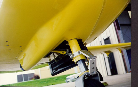
Retractable Landing Gear
Retractable Landing Gear for the Glasair Super II. Builder: Chris Yeeles - Glasair Super II, Gear, Glasair
Demating Glasair I RG Wreckage for Transport
And then there were two (big pieces). - Glasair I, Completed, Incident, Moving
Demating Glasair I RG Wreckage for Transport
The brute force method. Right side of wing had frozen into the ground. Dang, that spar is strong! (The left flap was already trashed) - Glasair I, Wing, Completed, Incident, Flaps, Moving
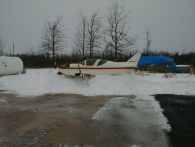
Transporting Glasair I RG Wreckage
Where do ya want it? - Glasair I, Completed, Incident, Moving
Transporting Glasair I RG Wreckage
Temporary Fuselage Storage - Glasair I, Fuselage, Completed, Incident, Moving
Transporting Glasair I RG Wreckage
Much warmer in Southern Florida! - Glasair I, Completed, Incident, Moving
Bonding in the A Rib
Bonding the A rib in the wing. Builder: Chris Yeeles - Glasair Super II, Wing, Glasair
GIII
Firewall completed with powder coat painted aluminum cover ready for engine re-install. - Glasair III, Engine, Fuselage, Paint, Firewall, Glasair
GIII 3262
Ready to re-install engine. - Glasair III, Engine, Glasair
GIII 3262
Detail of fuel line through firewall. - Glasair III, Engine, Fuel, Glasair
GIII #3262
Polish that stainless in exhaust tunnel! - Glasair III, Engine, Glasair
GIII #3262
Detail of hydraulic line through firwall. - Glasair III, Engine, Glasair
GIII #3262
Cabin heat firewall detail. - Glasair III, Engine, Glasair
GIII #3262
340 HP Lycoming left front cylinder. - Glasair III, Engine, Glasair
GIII #3262
Quadrant. - Glasair III, Interior, Controls, Glasair, Panel
Seat Pan Cutouts
Seat Pan Cutouts in the Super II wing. Buidler: Chris Yeeles - Glasair Super II, Wing, Glasair
GIII #3262
Quadrant guts. - Glasair III, Controls, Glasair
GIII #3262
AN3 bolt,AN970 washer, rod end on prop control lever. Those pesky cotters give me trouble! - Glasair III, Interior, Prop, Controls, Glasair
GIII #3262
Quadrant meets panel. - Glasair III, Panel, Interior, Glasair
Building Glasair Ailerons
Bonding in the inboard rib on a Glasair aileron. The rib is a 2-layer laminate that will have 5 additional layers of glass applied to it, 2 layers on the inside and 3 more layers on the outside after the aileron is closed. - Glasair, Wing, Ailerons
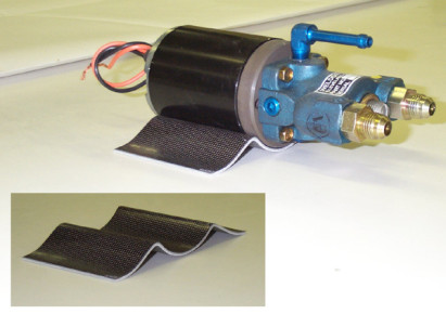
Fuel Pump Bracket
Carbon fiber fuel pump bracket. Builder: Allen Rockwell - Glasair, Fuel

GIII IO-540 Engine
Lyc IO-540 Enginge installed in Rod Benson's Glasair III. - Glasair III, Engine, Glasair
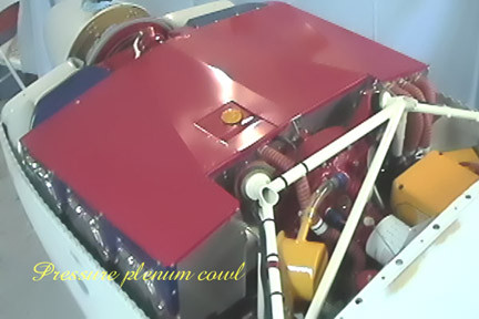
GIII3262
Pressure plenum - Glasair III, Engine, Glasair
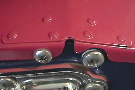
GIII3262
Pressure Plenum reinforcement close up detail - Glasair III, Engine, Glasair
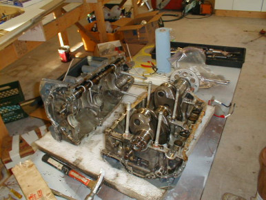
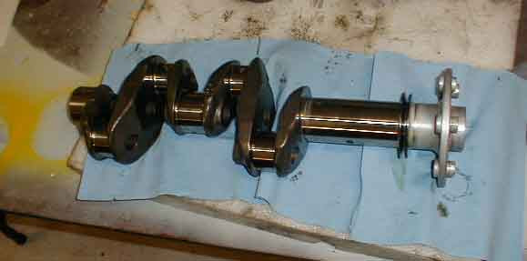
IO-360 Engine Disassembly
Tearing down my IO-360 for crank inspection and performance mods. - Glasair, Engine
IO-360 Engine Disassembly
Disassembling my IO-360 for crank inspection and performance mods. - Glasair, Engine
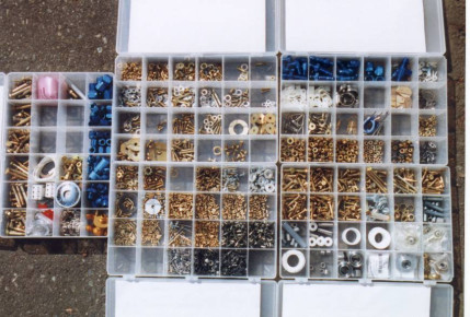
Hardware for the Super II
If there is any question about the completeness of a Glasair kit, here is a small bit of what comes with it. - Glasair Super II, Tools, Glasair
IO-360 Engine Teardown
Diving into the guts of my IO-360 - Glasair, Engine
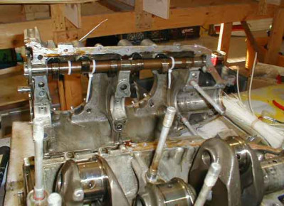
IO-360 Engine Teardown
It's actually a pretty basic engine. - Glasair, Engine
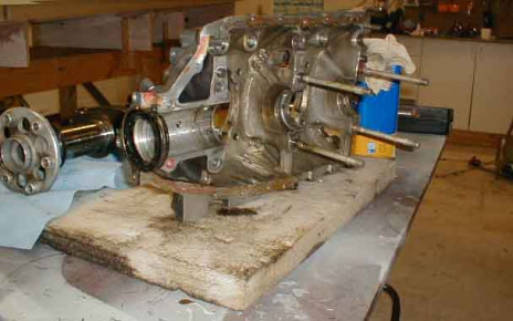
IO-360 Engine Teardown
I'm committed now...! - Glasair, Engine
IO-360 Engine Teardown
The parts now go out to various vendors for inspection and rework. - Glasair, Engine
Theo Green's Wing Jig Mod
Made 4 of clearance for gear to swing with wheel and gear door attached. - Glasair, Wing, Gear
Theo Green's Wing Jig Mod
Made 4 of clearance for gear to swing with wheel and gear door attached. - Glasair, Wing, Gear
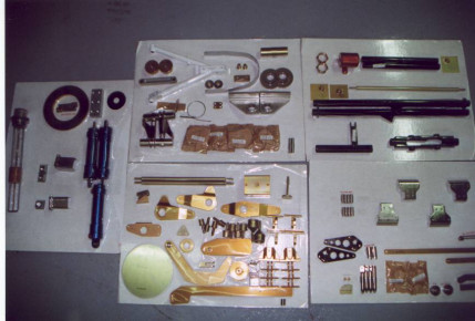
Machined parts for Super II
Here are just a few of the parts that come with the Super II kit, and how they are packaged. - Glasair Super II, Tools, Glasair

Theo Green's Wing Jig Mod
Glasair, Wing
ib-1681
Glasair
Theo Green's initial RG alignment
I used flat,square Al plates glued to the trunion bearing housings and rohacell shims sanded to match the contour under the bearings to get the height. When all the objectives were met, I indexed everything temporarilly with bondo and drilled the holes with the strut removed. - Glasair, Gear
The Wing in its jig
Here is the Super II wing in it's building jig. Builder: Chris Yeeles. - Glasair Super II, Wing, Glasair
Theo Green's initial RG alignment
I used flat,square Al plates glued to the trunion bearing housings and rohacell shims sanded to match the contour under the bearings to get the height. When all the objectives were met, I indexed everything temporarilly with bondo and drilled the holes with the strut removed. - Glasair, Gear
Theo Green's Roll Servo Mount
This is the mount I fashioned after Chris Yeeles'. Each side consists of two pieces of angle and one square Al side plate riveted together. Each side has two nutplates. I also fabricated the servo limiter underneath the pulley. - Glasair, Servo, Controls
Richard May's Glasair III
Xtended dorsal. Wing fillets. IO-540-S1A5 300hp engine overhauled. Nu-chrome cylinders. 2 blade Hartzell prop. Enlarged baggage compartment. - Glasair III, Wing, Engine, Fuselage, Prop, Glasair
Theo Green's Roll Servo Mount
This is the mount I fashioned after Chris Yeeles'. Each side consists of two pieces of angle and one square Al side plate riveted together. Each side has two nutplates. I also fabricated the servo limiter underneath the pulley. - Glasair, Servo, Controls
Theo Green's Roll Servo Mount
This is the mount I fashioned after Chris Yeeles'. Each side consists of two pieces of angle and one square Al side plate riveted together. Each side has two nutplates. I also fabricated the servo limiter underneath the pulley. - Glasair, Servo, Controls
Theo Green's Roll Servo Mount
This is the mount I fashioned after Chris Yeeles'. Each side consists of two pieces of angle and one square Al side plate riveted together. Each side has two nutplates. I also fabricated the servo limiter underneath the pulley. - Glasair, Servo, Controls
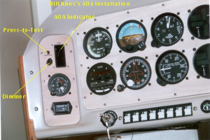
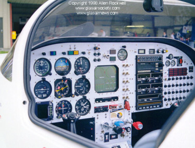
AOA Indicator In Glasair Panel
AOA Indicator In Glasair Future Vision Panel. Builder: Bill Knox - Glasair, Panel
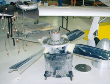
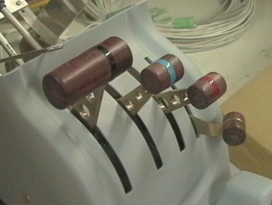
Hartzell governor bracket
two photos of the bracket and one installed - Glasair, Prop

hartzell governor bracket
Glasair, Prop
hartzell gogernor bracket
Glasair, Prop
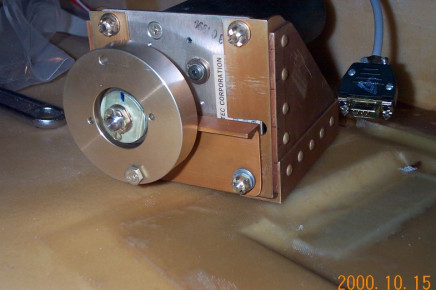
S-TEC Roll Servo
S-TEC Roll Servo installation in a G SII RG, image 1. - Glasair Super II, Wing, Servo, Glasair
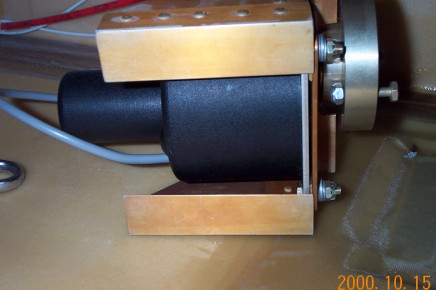
S-TEC Roll Servo
S-TEC Roll Servo installation in a S II RG, image 2 - Glasair Super II, Wing, Servo, Glasair
S-TEC Roll Servo
S-TEC Roll Servo installation in a S II RG, image 3 - Glasair Super II, Wing, Servo, Glasair
S-TEC Roll Servo
S-TEC Roll Servo installation in a S II RG, image 4 - Glasair Super II, Wing, Servo, Glasair
Panel Detail on N292RW
Ron Wilsons panel in Glasair I N292RW - Glasair I, Panel, Glasair
S-TEC Roll Servo
S-TEC Roll Servo installation in a S II RG, underside, image 1 - Glasair Super II, Wing, Servo, Glasair
S-TEC Roll Servo
S-TEC Roll Servo installation in a S II RG, underside, image 2 - Glasair Super II, Wing, Servo, Glasair
Aileron Pushrod Wind Boot
Aileron Pushrod Wind Boot on the B rib, left side - Glasair Super II, Wing, Ailerons, Glasair
Aileron Pushrod Wind Boot
Aileron Pushrod Wind Boot on the B rib, right side - Glasair Super II, Wing, Ailerons, Glasair
Rudder pedals
David Gauger's super IIs RG - Glasair II, Rudder, Fuselage, Glasair
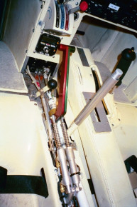
control tunnel Super IIs RG
bench assembling the control tunnel. It's easier to assemble things on a workbench than while laying on your side in the fuselage. SH never provided a good drawing of how to plumb the hydraulic lines - Glasair Super II, Wing, Fuselage, Controls, Glasair
fuel control valve
David Gauger's Super IIs RG - Glasair Super II, Fuel, Controls, Glasair
Flak Damage
April Fool! David Gauger's Super IIs RG - Glasair Super II-s, Fuselage, Glasair
Linkage slots in vert. stab.
Clearance slots in ribs C and D of the vertical stab. Builder: Allen Rockwell - Glasair Super II, Fuselage, Horizontal Stabilizer, Glasair
Interesting Inlets
Very interesting inlets on a Glasair. - Glasair, Cowl, Prop, Induction
Interesting Glasair Doors
Interesting Glasair Doors seen at Sun N Fun 2001 - Glasair, Fuselage, Completed, Window
Laminating the forward LG ribs
Laminating the forward LG ribs in the Super II FT. Builder: Allen Rockwell - Glasair Super II, Fuselage, Glasair
Instrument Panel on N540CM
Glasair, Panel
Retractable Steps
My steps retract by engine vacuum. - Glasair III, Engine, Glasair
Oxygen Manifold
Glasair III, Interior, Glasair
Hat Shelf
Glasair III, Interior, Glasair
Laminating the Dorsal.
Laminating the dorsal to the fuselage on the Super II. Builder: Allen Rockwell - Glasair Super II, Fuselage, Glasair
hydraulic manifold
I had to route the hydraulic lines around the corner of the seat pans because of conflicts with the slotted flap hinge Dave Gauger Super IIs RG - Glasair, Wing, Flaps
hydraulic manifold
detail of routing hydraulic lines along the aft shear web. hopefully the elevator push rod will not conflict with the hydraulic lines. There is no way to tell for sure untill I bolt the wing to the fusilage. One of SH's many annoying little ambiguities - Glasair, Wing, Elevator
Supercharged Subaru 6cyl
After experiencing many problems with dual turbo's, we retrofitted our Subaru SVX with a Vortec Supercharger. Plane: White Lightning - Glasair, Engine
Rear Windows Cut Out
Rear Windows Cut Out with 3/4 inch flange remaining. Builder: Allen Rockwell - Glasair Super II, Window, Fuselage, Glasair
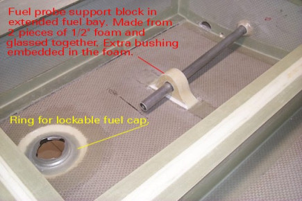
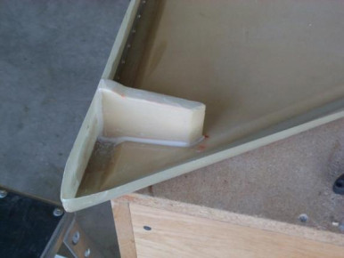
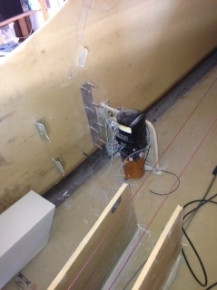
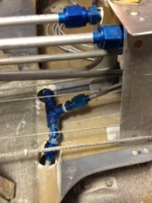
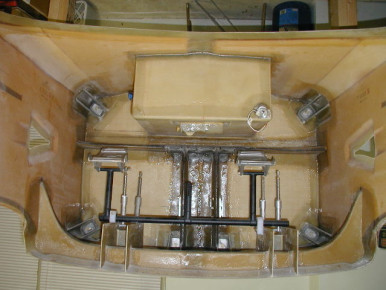
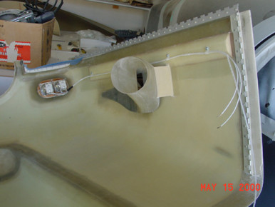
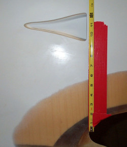
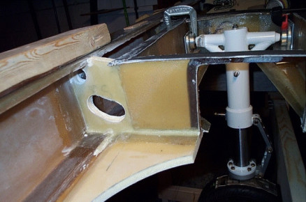
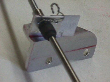
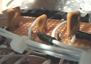
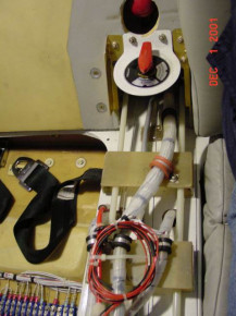
Fuel Probe Support
Fuel probe support in the extended fuel bay. Since Vision Micro requires that their probe be supported within the last four inches if there is no other support within 12 inches of the end, a block was made from two pieces of 1/2 foam. A counterbore on the interior sides of each piece allows room for epoxy/flox to hold the probe bushing in position. The two pieces are bonded together with epoxy/micro and bonded to the skin with micro. A layer of glass in on each face and 2 layers are laid up over the top to strengthen the bond with the wing. - Glasair, Wing, Interior, Fuel
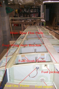
Left Wing Construction
Picture shows all of the fuel system installations and other steps in Chapter 7 of the Lancair Super ES Fastbuild Manual. - Glasair, Wing, Fuel
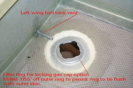
Extended Fuel Bay, Filler & Vent
Shows the fuel filler ring for the lockable gas cap option. The ring had to be milled .055 from the outer portion of the outer face of the ring to permit the filler to be mounted from the inside, per instructions for the conventional fuel filler asembly. This allowed the filler ring to protrude through the opening in the top skin and be slightly above the surface. When the wing is painted, the ring and the cap will be flush with the top skin. - Glasair, Wing, Fuel
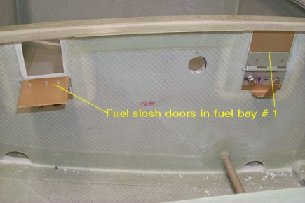
Lancair Super ES: Fuel Slosh Doors, Left Wing
Glasair, Wing, Fuel
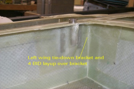
Lancair Super ES, Wing Tiedown Bracket
Glasair, Wing
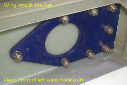
Lancair Super ES: Wing Attach Bracket
Shows the bracket installed. The slot in the fastbuild kit was too narrow and had to be ground out in some places to allow the bracket to be installed. In addition, the some of the holes in the fiberglass were not large enough to get the bolts through. Two were not perfectly aligned with the holes in the bracket. These holes had to be enlarged slightly to permit all of the bolts to be installed and torqued properly. Two bolts required 2 washers instead of the one specified. - Glasair, Wing
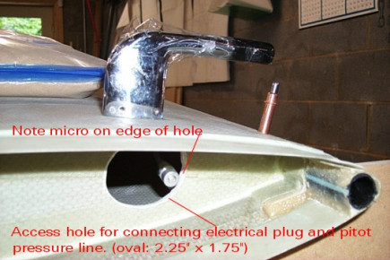
Lancair Super ES: Pitot Tube on Left Wing
Problem here was that of attaching and detaching the electrical and pressure connections to the tube. A larger access hole had to be made in the end rib to allow access and easy connections. - Glasair, Wing, Electrical
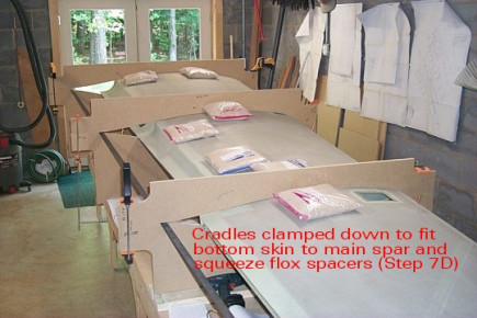
Lanceair Super ES: Wing Bottom Skin Fitting
The most critical step so far is number 7D. The gap between the main spar and the lower skin is set by putting 3 resin/flox pads on the spar and squeezing them down with the bottom skin installed and the cradles clamped tightly. This sets the overall height of the main spar and the height to which the spar is built up in subsequent steps. The factory tech support says that between 500 and 700 pounds of weight and cradle clamping will be needed for wing closeout. A good bond at the main spar is essential and the weight helps achieve this. - Glasair, Wing
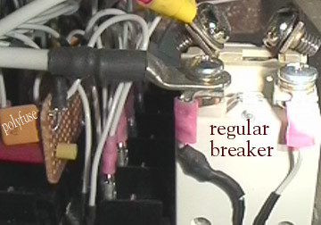
GIII kit 3263
polyfuse to breaker comparison - Glasair III, Glasair
GIII kit 3263
fuse panel with rocker switches and LED - open circuit indicators - Glasair III, Panel, Glasair
GIII kit 3263
fuse panel with rocker switches and LED open circuit indicators - Glasair III, Panel, Glasair

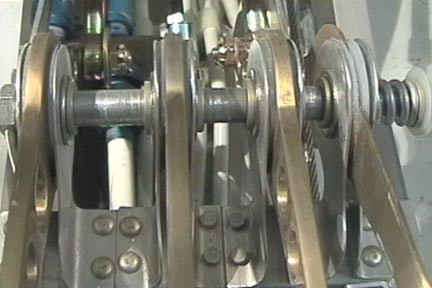
Flap Actuator Detail
Detail of the flap actuator on a Glasair Super II RG - Glasair Super II, Wing, Flaps, Glasair
Flap Control Sleeve
Drawing of the Glasair flap control sleeve - Glasair Super II, Wing, Flaps, Controls, Glasair
Planes at Sun-n-Fun 2001
Glasair, Prop, Cowl
Panel on N540GL
Panel on N540GL. A Garmin GPS III mounted using a simple bracket. ired into a breaker, the Garmin offers tremendous redundency -- if the power is interrupted or fails, the Garmin simply reverts to it's internal AA batteries. Builder: Evan Julber. - Glasair III, Panel, Glasair
Planes at Sun-n-Fun 2001
Glasair, Panel, Completed
Planes at Sun-n-Fun 2001
Rear Space Maximized - Glasair, Fuselage
Planes at Sun-n-Fun 2001
Glasair, Interior
Planes at Sun-n-Fun 2001
Glasair, Completed, Events, Interior, Window
Planes at Sun-n-Fun 2001
Glasair, Completed, Events, Seat, Panel
Planes at Sun-n-Fun 2001
Glasair, Completed, Panel
Planes at Sun-n-Fun 2001
Glasair, Completed, Events, Seat, Interior
Primer on the Dorsal area.
First coat of primer on the dorsal area of Allen Rockwell's Glasair Super II - Glasair Super II, Fuselage, Glasair
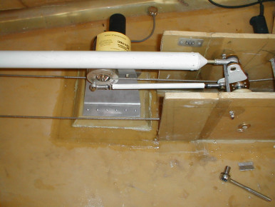
autopilot pitch servo installation
Pitch servo installed on 3/4 thick mounting pad. This is easily varied depending on the individual installation. The thing to watch here is that the rudder cable clears everything. I used the standard S-H mount brackets. The pushrod for my installation is about 12.5 center to center, once again it is easily varied. I made the pushrod from .032 x .5 4130. Nothing special about the size, it just happened to be what I had sitting around. - Glasair, Rudder, Servo, Controls, Autopilot
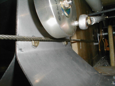
autopilot pitch servo installation
Here is the bellcrank end of the pushrod. Jam nuts are not tightened as the installation is just temporary. The Heim bearings came from ACS. They had some surplus ones for just a little over half the price of new. - Glasair, Servo, Controls, Autopilot
autopilot pitch servo installation
Closeup of the pushrod flywheel. Note the spacer between the Heim bearing and the flywheel. - Glasair, Servo, Controls, Autopilot
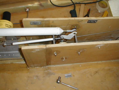
autopilot pitch servo installation
Closeup of the rudder cable to show clearance between servo mount and mounting hardware. - Glasair, Rudder, Servo, Controls, Autopilot
autopilot pitch servo installation
Pic of pushrod bracket prior to cleanup and riveting to elevator bellcrank. The bracket is made from .050 4130, once again it's what I happened to have laying around the shop. The rivet laying to the right just happened to sneak into the photo and is not the length that I used. - Glasair, Elevator, Servo, Controls, Autopilot
Mike Smith's G-II RG
Mike Smith's G-II RG up on it's gear. - Glasair II, Fuselage, Gear, Glasair
autopilot pitch servo installation
Pic of pushrod bracket prior to cleanup and riveting to elevator bellcrank. The bracket is made from .050 4130, once again it's what I happened to have laying around the shop. The rivet laying to the right just happened to sneak into the photo and is not the length that I used. - Glasair, Elevator, Servo, Controls, Autopilot
inner cowl
This cowl has enabled me to reduce the total air intake to 17 sq ins and given a substantial speed increase. John de Frayssinet Glasair 1 RG - Glasair, Cowl, Induction, Engine
hand brakes for disabled pilot
I have replaced the toe brakes with handbrakes. These work real well for every one. John de Frayssinet G-BMIO Glasair 1 RG - Glasair, Controls, Panel
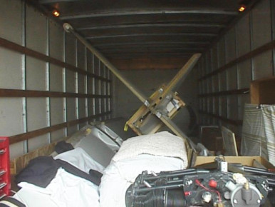
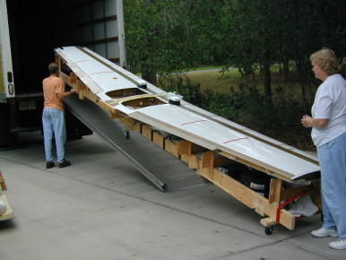
Moving a Glasair Project - 1
This and a companion image shows how I packed my project into a Ryder truck for a successful 800-mile trip. - Glasair, Moving
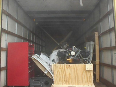
Moving a Glasair - 2
This and a companion image shows how I packed my project into a Ryder truck for a successful 800-mile trip. - Glasair, Moving
Mike Smith's G-II RG
Mike Smith's G-II RG up on it's gear. - Glasair II, Fuselage, Gear, Glasair
Mike Smith's G-II RG
Mike Smith's G-II RG just prior to mating the wing. - Glasair II, Wing, Fuselage, Glasair
Arlington 01
Defroster vent - Glasair, Interior
Firewall Bulkhead
Aft side of firewall bulkhead with engine mount reinforcement support laminates Q-celled in place. Builder: Byron J. Covey - Glasair Super II, Engine, Fuselage, Firewall, Glasair
Arlington 01
Center console of N22HC with power levers - Glasair, Panel
Arlington 01
Center console of N706C - Glasair, Panel
Arlington 01
Cockpit of N22HC - Glasair, Panel
ib-1859
Rudder, Horizontal Stabilizer, Glasair
Firewall Bulhead fwd side
Cloth in place for the first of three laminates on the forward side of the firewall bulkhead. Yes, the cloth can fit flat in the corners by working it after it is wetted out. Builder: Byron J. Covey - Glasair Super II, Fuselage, Firewall, Glasair
Arlington 01
Great looking panels - Glasair, Panel
Pilot on Right Instrument Panel
From N196G - Glasair, Panel
Instrument panel
Instrument panel installed in a Lancair 4 - Glasair, Panel
Glasair 1 RG G-BMIO
Instrument panel with handbrakes for disabled pilot - Glasair, Panel, Interior
G-BMIO Glasair 1 RG tail skid probs
tail skid modified to house strobe. Moulded in poly-carbonate - Glasair, Fuselage
ib-1868
Fuselage, Glasair
ib-1869
Fuselage, Glasair
Laminating engine mount supports
Laminating in progress, with 4 more layers to go on the inside for the nose gear support gussets. Builder: Byron J. Covey - Glasair Super II, Engine, Fuselage, Gear, Glasair
ib-1871
Glasair
ib-1872
Glasair
ib-1873
Glasair
ib-1875
Glasair
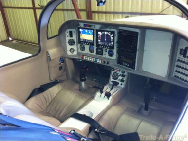
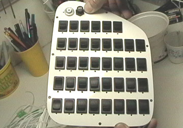
Panel N964AM
Mark Anderson Super IIFT panel under construction at Aerotronics. Have the final product at home and can't wait to install it. - Glasair Super II, Panel, Glasair
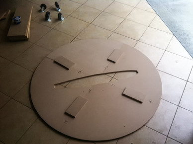
Yet another wing jig
I built this jig, which allows full wing rotation, to ease my painting prep pain. - Glasair, Wing, Tools
Fuselage jig
I built this jig, which allows the fuselage to rotate about +- 45 degrees, to simplify painting and painting prep. This shows the fuselage at 45 degrees. The next image shows the jig details. - Glasair, Fuselage, Paint, Moving
Cabin Air Ducts
Bonding in the cabin air ducts on a Glasair Super II-S. Builder: Allen Rockwell - Glasair Super II, Fuselage, Glasair
Fuselage jig
This shows the jig details. It is attached to the wing support points of the fuselage, and pivots on a pipe. - Glasair, Wing, Fuselage, Moving
Moving a Glasair project
Converted the wing jig into a dolly by adding 6 casters. Added a floor to save space, and put the flaps, ailerons and other parts under the wing to save space in the 24 foot Ryder truck. Put foam pipe insulation between the wing and the jig to help cushion the wing. - Glasair, Wing, Flaps, Moving
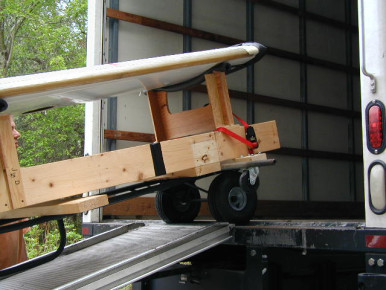
Moving a Glasair project
Used a hand truck to roll the wing / jig up the ramp. The casters were mounted on 2X4s that extended wider than the ramp for stability. - Glasair, Wing, Horizontal Stabilizer, Moving
Moving a Glasair project
The fuselage went over the wing to save space for everything else. Tools, parts, misc. airplane parts collected over the years added up to a full load. The forward fuselage support is cushioned with foam, and the aft fuselage is supported with foam on the wing directly over a rib and a jig support. The only damage was on the engine mount, where the big cardboard box that contains the rudder kit rubbed against the powder coat and removed some of the paint in an area about 1/2 inch long. It did not go through to bare metal, but if you move a project, check for rubbing between parts / boxes. - Glasair, Wing, Engine, Rudder, Fuselage, Paint, Moving
Glasair Moving
Glasair ready to move to it's new home. It needed to be tilted to 45 degrees to allow it to fit inside a moving van. - Glasair, Moving, Engine, Fuselage
Glasair Moving
Glasair ready to move to it's new home. It needed to be tilted to 45 degrees to allow it to fit inside a moving van. - Glasair, Moving, Engine, Fuselage
Moving A Glasair
Glasair ready to move to it's new home. It needed to be tilted to 45 degrees to allow it to fit inside a moving van. - Glasair, Moving
Formica panel
Pic of Formica glued back-to-back for instument panel. The holes were cut using a Starrett 3 1/8 bimetal hole saw from the face side. The small cutouts for the altimeter and VSI were rough cut using a Dremel hobby jigsaw and then filed to final shape. I used the template from Panel Planner software to locate the holes for the main cutouts and the screw holes and they are right on the money. I held the template in place with double face tape. There are still a number of holes to cut yet...clock, suction guage, etc. The color of the Formica is not my favorite but it was cheap and this is a go plane and not a show plane. - Glasair, Panel
Moving A Glasair
Hiring a moving van is the answer ...lots of room, good ramps, lots of padding and straps. An entire Glasair Super II RG and all parts was loaded and on the road in less than an hour. All that's left now is the crying 🙁 - Glasair, Moving
Engine Mount Holes
Just drilled 3/8 engine mount hole. Detail photo shows what the engine mount area looks like inside the fuse. Builder: Allen Rockwell - Glasair Super II, Engine, Fuselage, Glasair
Moving A Glasair
Hiring a moving van is the answer ...lots of room, good ramps, lots of padding and straps. An entire Glasair Super II RG and all parts was loaded and on the road in less than an hour. All that's left now is the crying 🙁 - Glasair, Moving
Scoring Tool For The Firewall Bulkhead
This is the tool that I made for scoring a 1/8 deep cut in the Rotacell foam panel for the firewall bulkhead. I it is made from 1 aluminum angle stock with a sharp blade fastened at a slight angle. When used with a straight edge, clamped to the worktable, it really cut the time required to perform all those cuts. - Glasair, Engine, Firewall
Too Close To My Sanding...
My wife caught me getting too close to my work. She burst out laughing and made me wait while she got a camera. I was standing there wondering what on earth was she laughing at. Since this picture was taken, I have been using a dust mask. - Glasair
Joining Both Fuselage Halves Together
I found that duct tape slipped alot, I decided to use tongue depressors and hot glue. As you can see, I used A LOT of tongue depressors. I think the grand total was 103 depressors. I learned later that this was way too many. - Glasair, Fuselage
Ready To Start Fiberglassing
The fuselage is joined together by (way TOO MANY) tongue depressors and shipping tape. One good thing was that the fuselage did not shift any when I was fiberglassing. - Glasair, Fuselage
Tongue Depressors!
This is me removing all those darned tongue depressors and hot glue. It took a long time and I was very DEPRESSED! The hair dryer helped greatly. Oh well, a lesson learned is never forgotten. Sure....... - Glasair, Fuselage
Working On The Belly Panels
The aft belly panel is ready for fiberglassing. Thank God for ropes and rafters. - Glasair, Fuselage, Panel
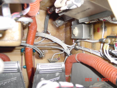
Electrical
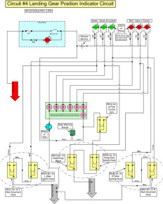
Redrawn schematics for clarity and customization - Glasair, Panel, Electrical, Gear
Dace Kirk's Panel
N115DK At Arlington 98. Dace Kirk's Glasiar III panel - Glasair III, Panel, Completed, Glasair
Leading Edge Extension (LEX)
Leading Edge Extension (LEX) on Tom Taylor's Glasair II-s - Glasair II, Wing, Glasair
Air inlets
New oval inlet rings for Gll and Glll machined with special airfoil section on inside and securing groove on outside - Glasair, Cowl, Completed, Prop
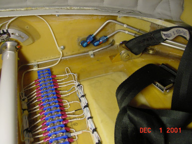
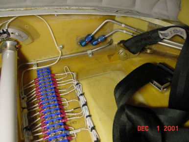
CP Seatpan Wiring #1 - N15F
Glasair, Wing, Electrical
CP Footwell Wiring #1 - N15F
Glasair, Interior, Electrical
CP Seatpan Wiring - N15F
Glasair, Wing, Electrical
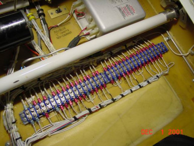
CP Seatpan Wiring - N15F
Glasair, Wing, Electrical
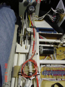
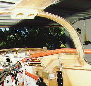
Center Console Wiring - N15F
Glasair, Panel, Electrical
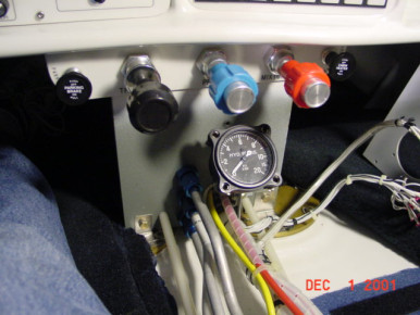
Center Console Wiring - N15F
Glasair, Wing, Electrical
Center Console Wiring - N15F
Glasair, Wing, Electrical
Center Console Wiring - N15F
Glasair, Wing, Electrical
Spoiler on N24TX
Detail of Spoiler on tom taylor's N24TX. Tom claims that these spoilers eliminate 10 percent of the wings total lift. - Glasair II, Wing, Glasair
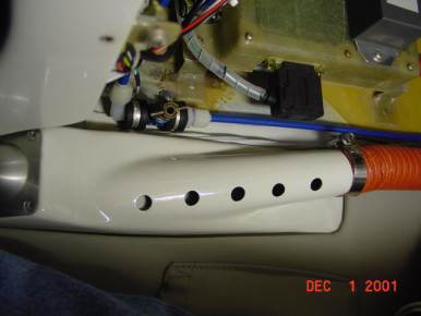
Cabin Heater Vent - N15F
Glasair, Interior
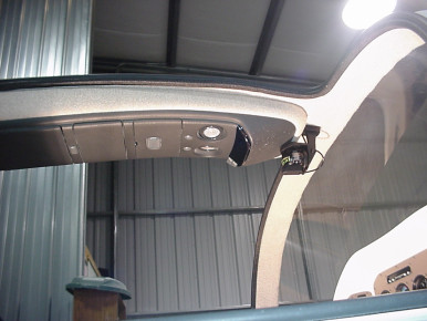
Overhead Consloe
This is a overhead console I took out of a 97 Blazer. I modifed the sides to fit the top and covered it with the head liner material. I have hooked up the outside air temp. and the map and bagage lights. It also has a place for sunglasses and a CD player. - Glasair, Interior
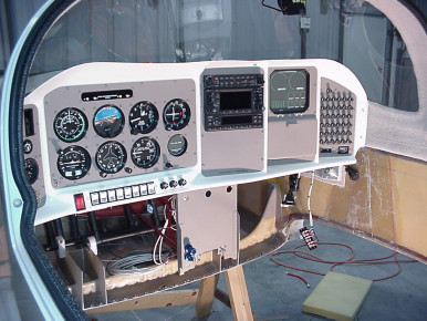
Instrument Panel
Aerotronics panel installed. - Glasair, Panel
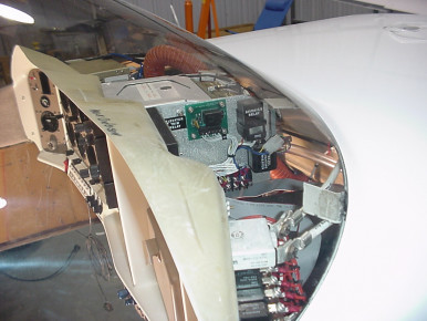
Instrument panel back
Looking at the top of panle - Glasair, Panel
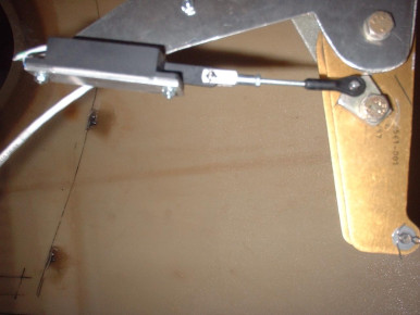
elevator trim transponder
elevator trim MAC transponder for electronic indicator mounted near to the elevator Bellcrank with concentric adjustment bolt. - Glasair, Elevator, Trim, Electrical, Controls
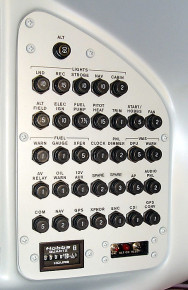
Glastar - Circuit Breakers
Glasair, Panel
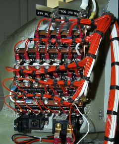
Circuit Breaker Wiring
From Glastar site - Glasair, Panel, Electrical
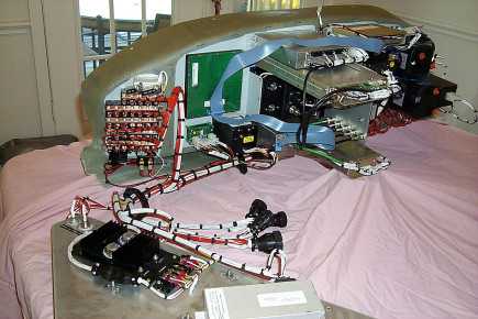
Instrument Panel Wiring #1
Glasair, Panel, Electrical
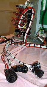
Instrument Panel Wiring
Glasair, Panel, Electrical
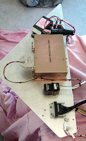
VM-1000 DPU Wiring
Glasair, Panel, Electrical
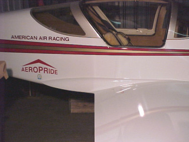
Trailing edge extension
Trailing edge extension on Tom Taylors Glasair II-S N24TX - Glasair II, Wing, Glasair
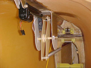
Electric Elevator Trim
This is the Emerald Aircrafters electric trim setup. - Glasair Super II, Elevator, Trim, Electrical, Controls, Glasair
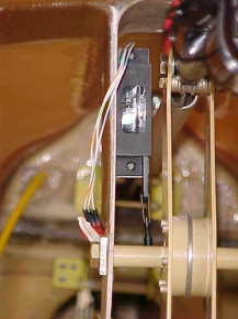
Elevator Trim Transducer
This is a MAC Transducer used in conjunction with the Emerald Aircrafters electric trim setup - Glasair Super II, Elevator, Trim, Electrical, Controls, Glasair
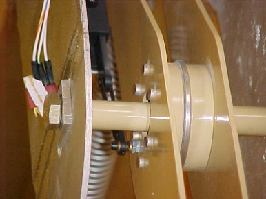
Trim Transducer Actuator
Closeup of hardware (model car parts) used to attach MAC transducer to the elevator bellcrank - Glasair Super II, Elevator, Trim, Controls, Glasair
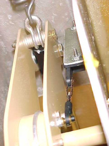
More trim transducer stuff
Close up from the rear of the MAC trim transducer showing bracket and attachment to the bellcrank - Glasair Super II, Wing, Trim, Controls, Glasair
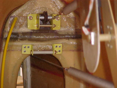
Electric Trim Pully
This shows the modification to the trim pullys for the Emerald Aircrafters elevator trim setup. Note that the top pully is upside down compared to the standard plans. The lower pully was improvised to eliminate chaffing on the top of the bulkhead. - Glasair Super II, Elevator, Trim, Electrical, Controls, Glasair
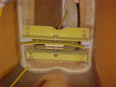
Rudder Bellcrack
Rudder bellcrank closeup Glasair SIIS FT. - Glasair Super II, Rudder, Controls, Glasair
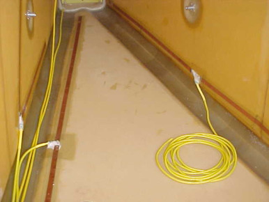
Antenna
Com, Mkr Bkn, and FM. - Glasair Super II, Fuselage, Glasair
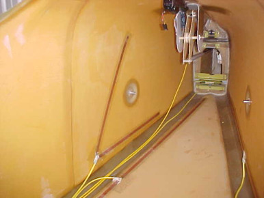
Fuselage -Rear view
Shows Electric Trim, Antenna locations and Static ports. - Glasair Super II, Fuselage, Trim, Electrical, Glasair
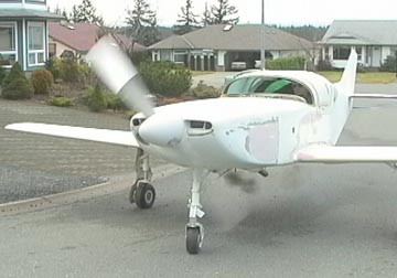
First Engine Start
Started first try - woke up the neighbors - everything works - so far. Big grins here. Hope to fly this summer. - Glasair, Engine
Folding Cloth Cutting Table
The design for this table was found on Marv Kayes Lancair site. I have found it quite a space saving idea in my workshop, thanks to Marv for allowing me to use his design. Paul Pengilly Glasair Super II RG # 2428 - Glasair, Wing, Tools
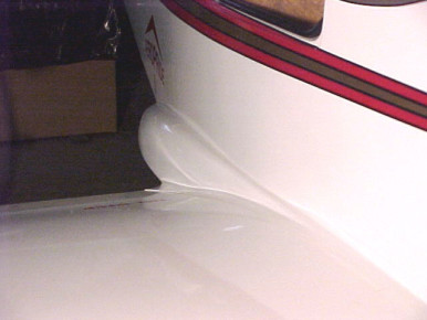
Trailing edge extension
Trailing edge extension / aft wing fairing on Tom Taylors Glasair II-S N24TX - Glasair II, Wing, Fuselage, Glasair
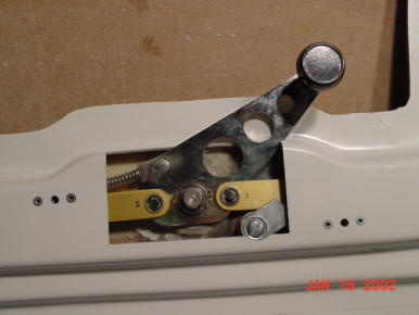
N51AR - Door Latch
Glasair, Fuselage, Window
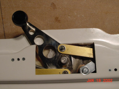
N51AR - Door Latch
Glasair, Fuselage, Window
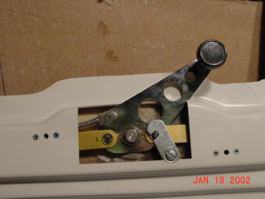
N51AR - Door Latch
Glasair, Fuselage, Window
N51AR - Door Latch
Glasair, Fuselage, Window
ib-1934
Flaps, Controls, Seat, Glasair
ib-1936
Engine, Firewall, Glasair
ib-1937
Engine, Glasair
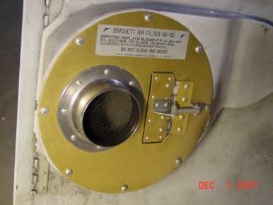
Induction Assembly - N15F
Neil Garvin's alternate air door & induction - Glasair, Cowl, Induction
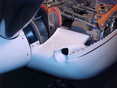
Ram air intake
Ram air intake on Tom Taylors Glasair II-S N24TX. This mod eliminates the NACA scoop on the side of the fairing. - Glasair II, Engine, Induction, Cowl, Glasair

Induction Assembly - N15F
Neil Garvin's alternate air door & induction - Glasair, Cowl, Induction
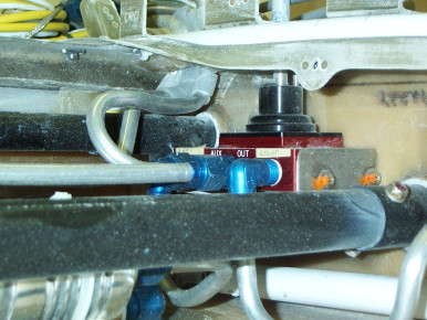
Fuel Valve
Installation of Jim Roberston's fuel valve inside the wing with split wing tanks. - Glasair, Wing, Fuel
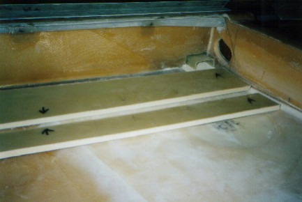
Aft Fuel Bays
Aft Fuel bays forward bulkhead utilizing Main Spar Cap - Glasair, Wing, Fuel
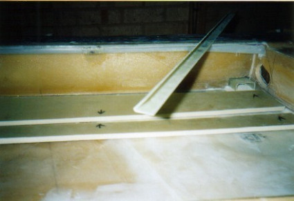
Aft Fuel Bays
Aft Fuel bays forward bulkhead utilizing Main Spar Cap - Glasair, Wing, Fuel
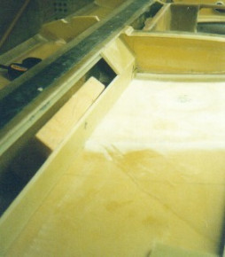
Aft Fuel Bays
Aft Fuel bays forward bulkhead utilizing Main Spar Cap - Glasair, Wing, Fuel
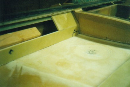
Aft Fuel Bays
Aft Fuel bays forward bulkhead utilizing Main Spar Cap - Glasair, Wing, Fuel
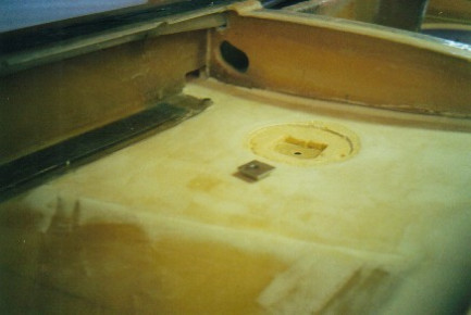
Aft Fuel Bays
Aft Fuel bays forward bulkhead utilizing Main Spar Cap - Glasair, Wing, Fuel
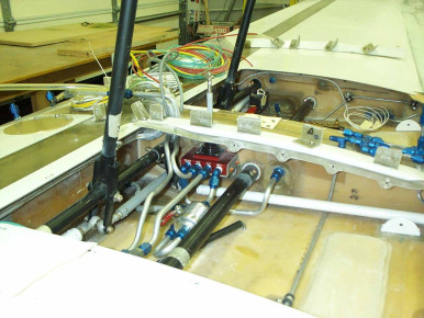
Fuel Valve installation
This is Jim Robinson's fuel valve modified for installation inside the left seat pan area. Selector shaft come up through console in normal position. system has ball shutoff valve and 10 micron filter btw pickup and valve, both sides. - Glasair, Fuel
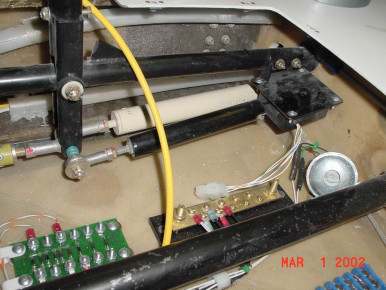
Phoenix Composites Aileron Trim
Glasair, Trim, Ailerons, Controls
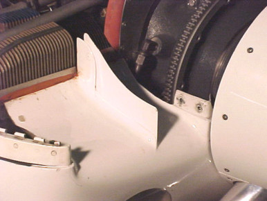
Engine air inlet
Engine air inlet on Tom Taylors Glasair II-S N24TX. The vertical splitter vane keeps air from taking aright turn when it reaches the taller outboard cooling vanes. - Glasair II, Engine, Glasair
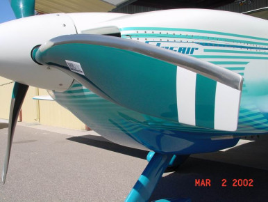
Whirlwind Prop - N944G
Glasair, Prop
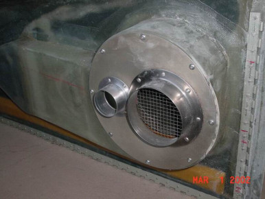
Air Induction - Phoenix Composites
Glasair, Engine, Induction, Cowl
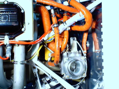
Fuel induction plumbing
Glasair, Engine, Induction, Fuel
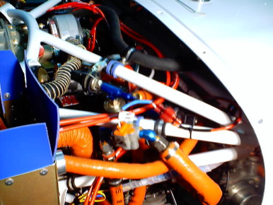
Induction plumbing
Glasair, Engine, Induction
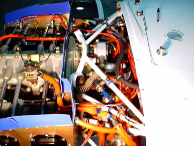
Firewall forward
Glasair, Engine, Firewall
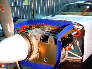
Baffling
Glasair, Engine
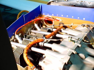
Baffling
Glasair, Engine
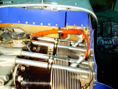
Baffling
Glasair, Engine
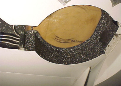
Wheel well
Wheel well for the RH main on Tom Taylors Glasair II-S N24TX. - Glasair Super II, Gear, Glasair
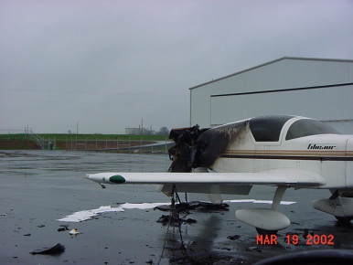
Lightning damage
Glasair, Incident
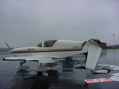
Lighting damage Lighting damage
Glasair, Incident
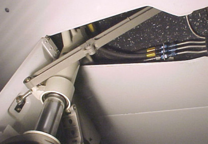
Landing gear strut
Landing gear strut on Tom Taylors Glasair II-S N24TX. - Glasair II, Gear, Glasair
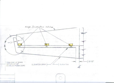
Hinge Inspection Hatches
Glasair, Horizontal Stabilizer
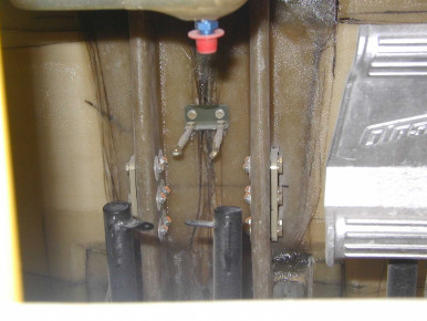
ib-1975
Glasair
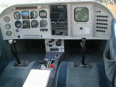
Instrument Panel, N902S
At lakeland, 2002 - Glasair, Panel
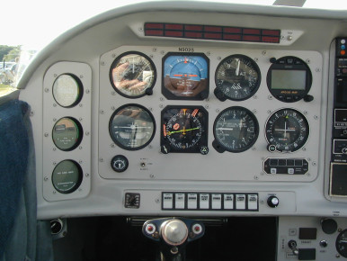
Instrument Panel, N902S
OLYMPUS DIGITAL CAMERA - Glasair, Panel
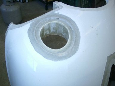
ib-1978
Cowl, Glasair
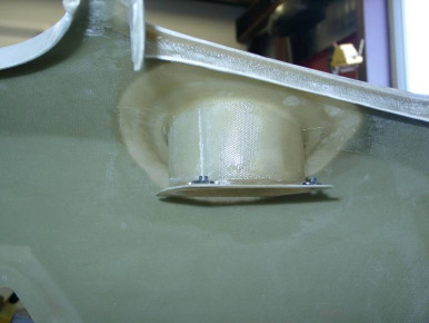
ib-1979
Cowl, Electrical, Lighting, Glasair
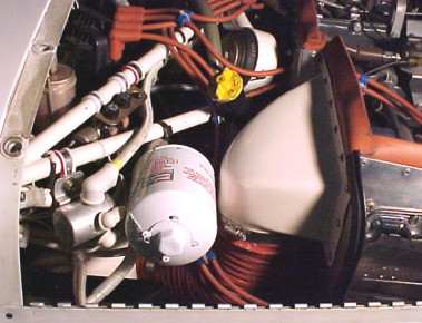
Oil cooler
Oil cooler installation on Tom Taylors Glasair II-S N24TX. Tom used a Glasair III oil cooler due to the 200hp engine and high temperatures encountered in the southwest US. - Glasair II, Engine, Glasair
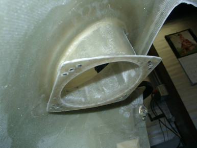
ib-1980
Cowl, Electrical, Lighting, Glasair
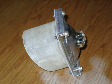
ib-1981
Electrical, Cowl, Lighting, Glasair
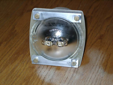
ib-1982
Cowl, Electrical, Lighting, Glasair
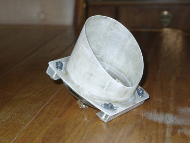
ib-1983
Cowl, Electrical, Lighting, Glasair
ib-1984
Seat, Glasair
ib-1985
Seat, Glasair
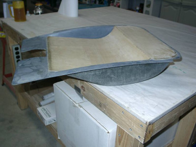
ib-1986
Seat, Glasair
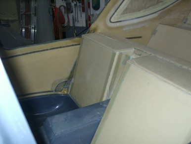
ib-1987
Seat, Glasair
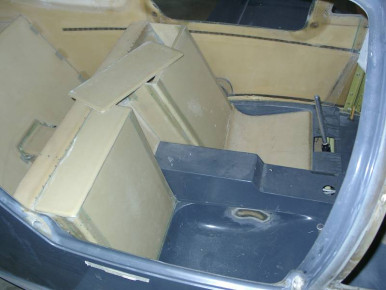
ib-1988
Seat, Glasair
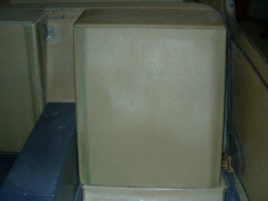
ib-1989
Seat, Glasair
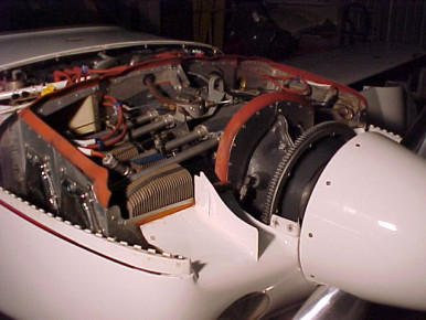
Engine detail
Photo of the 200hp Lycoming IO-360-C1C in Tom Taylors Glasair II-S N24TX. - Glasair II, Engine, Glasair
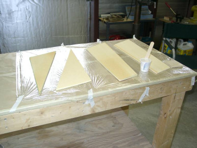
ib-1990
Glasair
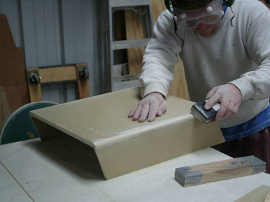
ib-1991
Seat, Glasair
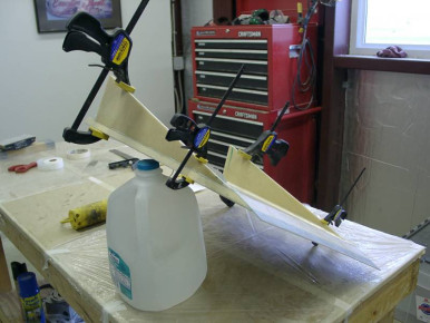
ib-1992
Seat, Glasair
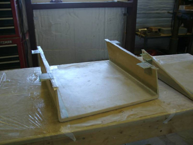
ib-1993
Seat, Glasair
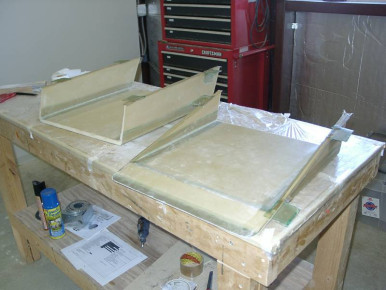
ib-1994
Seat, Glasair
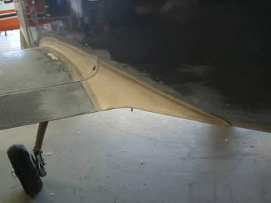
ib-1995
Wing, Fuselage, Glasair
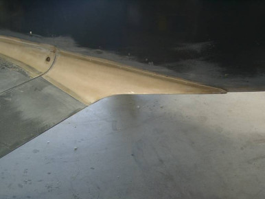
ib-1996
Wing, Fuselage, Glasair
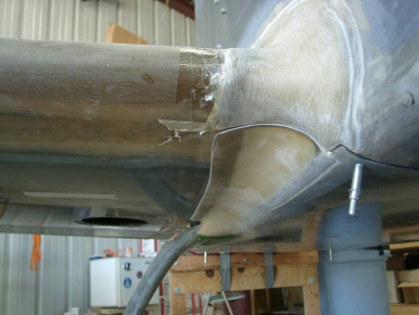
ib-1998
Gear, Glasair
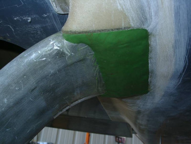
ib-1999
Gear, Glasair
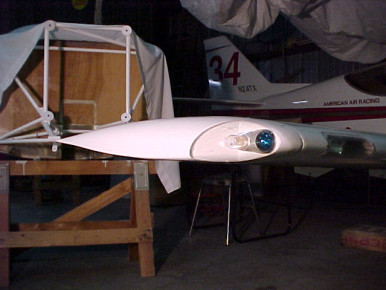
Wingtip detail
Wingtip of Tom Taylors Glasair II-S N24TX. This wingtip is available from Aeropride Technology and helps eliminate the wingtip vorticies asssociated with the standard wingtips. - Glasair II, Wing, Glasair, Wingtip
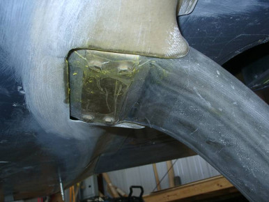
ib-2000
Gear, Glasair
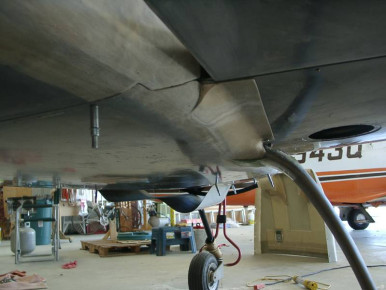
ib-2001
Gear, Glasair
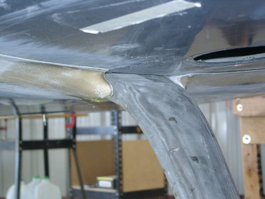
ib-2002
Gear, Glasair
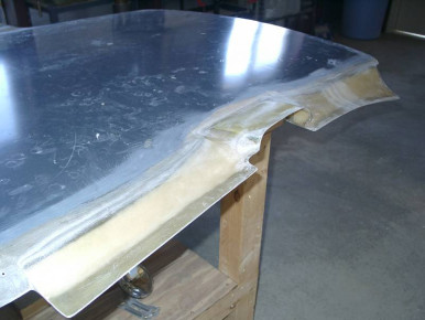
ib-2003
Glasair
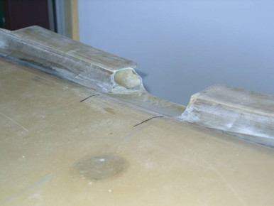
ib-2004
Glasair
ib-2005
Glasair
ib-2006
Glasair
Blue Mountain EFIS
Glasair, Panel
Blue Mountain EFIS
Glasair, Panel
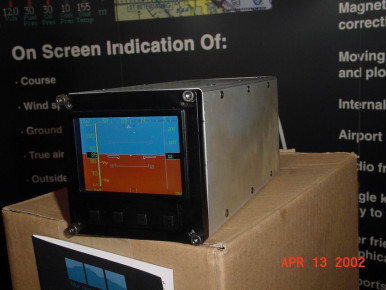
Blue Mountain EFIS
Glasair, Panel
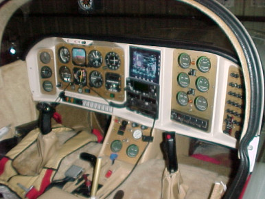
Panel in N24TX
Panel in Tom Taylors Glasair II-S N24TX. - Glasair II, Panel, Glasair
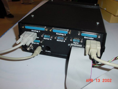
Blue Mountain EFIS
Glasair, Panel
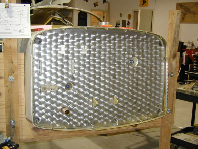
ib-2011
Firewall, Glasair
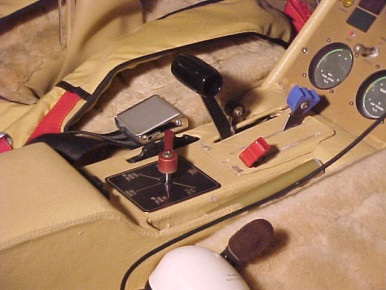
Spoiler actuator
Spoiler actuator in Tom Taylors Glasair II-S N24TX - It's the gold anodized lever on the right side of the center console. - Glasair II, Interior, Glasair
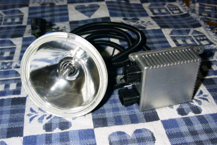
ib-2020
Electrical, Lighting, Glasair
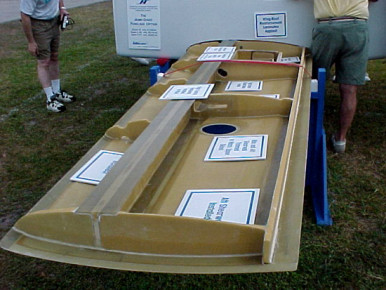
Glasair Jump-Start Wing
Detail photo of the Glasair Jump-Start Wing option. - Glasair Super II, Wing, Glasair
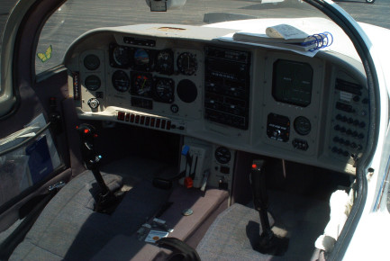
N676EC Interior
Dr Joe Castle's II-S RG From Marietta,OH - Glasair, Panel, Interior
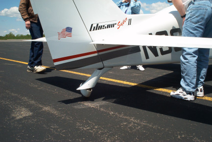
Marysville Fly-In
Mark Mosers's Super II-S TD N36MS with a super paint job and custom made decals - Glasair, Completed, Paint, Gear, Rudder
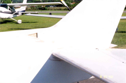
Bodywork Tail
Glasair
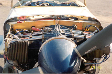
Up close engine detail
Glasair, Engine
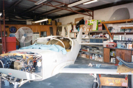
Bodywork
Glasair, Wing
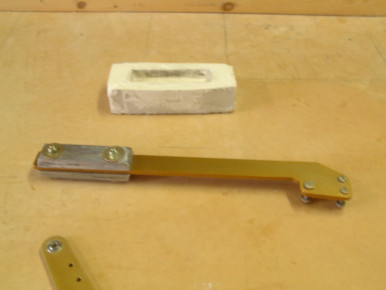
Elevator Counter Weight
Elevator counter weight made using a plaster mould - Glasair, Elevator, Horizontal Stabilizer
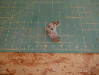
Induction elbow support bracket
Here is the raw bracket I fabricated to carry the induction elbow support bracket. This photo was taken prior to cleanup and painting. I made the bracket from some 4130 that I had alying around the shop. - Glasair, Engine, Paint, Induction
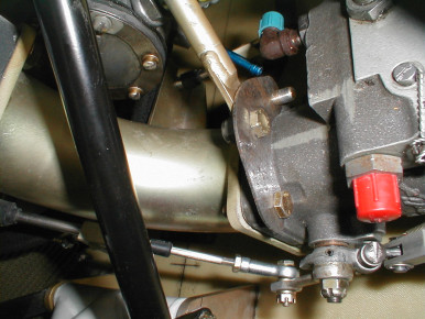
Induction elbow support
This photo is of the fabricated bracket set in place temporarily. Photo is taken from below. - Glasair, Engine, Induction
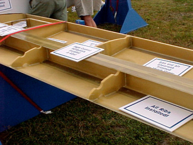
Glasair Jump-Start Wing
Detail photo of the fuel cell baffles in the Glasair Jump-Start Wing - Glasair Super II, Wing, Fuel, Glasair
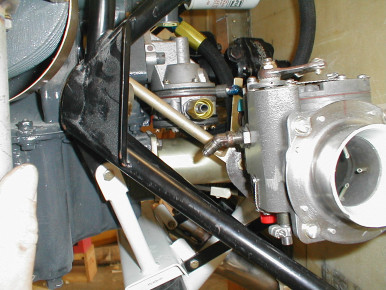
Induction elbow support
Here is a photo showing the revised position of the induction elbow support bracket. Plenty of room now for the fuel pump outlet. Fuel pump outlet has fitting attached just for photo purposes. - Glasair, Wing, Engine, Induction, Fuel
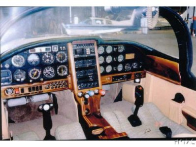
N789PB Interior
N789PB interior (picture from e-bay) - Glasair, Interior, Panel
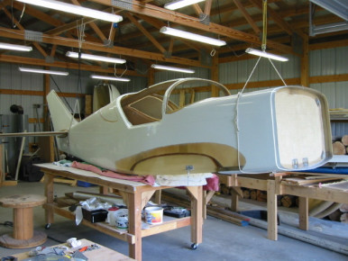
Preparing to Laminate Stabilizer inside the Fuselage
I removed my Super II-S FT from it's three point stand and onto a work table. I was easily able to crawl inside the fuselage and laminate the horizontal stabilizer to the fuselage. I used a 24 fan to blow away the fumes and cool me off. Luckly, a neighbor helped apply the laminates from the rear by reaching in aft opening. - Glasair Super II, Fuselage, Horizontal Stabilizer, Glasair
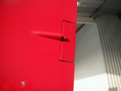
GIII Rudder MAC Trim
Left side of the rudder with electric MAC trim tab installed on GIII built by Rod Benson. - Glasair III, Rudder, Trim, Electrical, Glasair
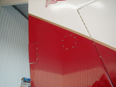
Rudder trim tab MAC on Rod Benson's GIII
Right side of the electric MAC rudder trim tab installed on Rod Benson's GIII. - Glasair III, Rudder, Trim, Electrical, Glasair
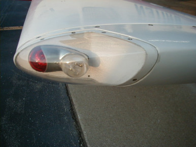
Wing tip nav/strobe light on Rod Benson's GIII
Nav/strobe light on the short wing tip with painted blackground for reflection. - Glasair III, Wing, Electrical, Lighting, Glasair, Wingtip

Extended Wing tip nav/strobe light on Rod Benson's GIII
Extended wing tip nav/strobe light with a polished alum. background for reflection. - Glasair III, Wing, Flaps, Electrical, Lighting, Glasair, Wingtip
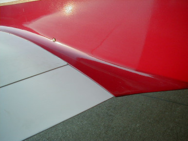
Flap/fuselage transition on Rod Benson's GIII
Top view of the flap/fuselage connection on Rod Benson's GIII. - Glasair III, Fuselage, Flaps, Ailerons, Glasair
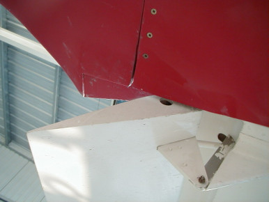
Flap/fuselage transition on Rod Benson's GIII
Bottom view of the transition between the fuselage and the flap. - Glasair III, Fuselage, Flaps, Ailerons, Glasair
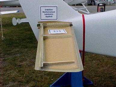
Glasair Jump-Start Horizontal
Glasair Jump-Start Horizontal stabilizer - Glasair Super II, Horizontal Stabilizer, Glasair
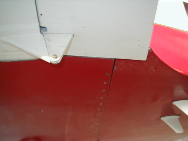
Flap/fuselage transiton on Rod Benson's GIII
Bottom view of the flap/fuselage transiton with the flap up. - Glasair III, Fuselage, Flaps, Ailerons, Glasair
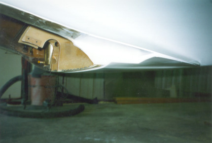
ib-2051
Glasair
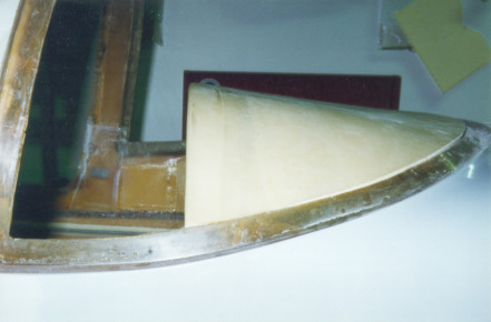
ib-2052
Window, Glasair
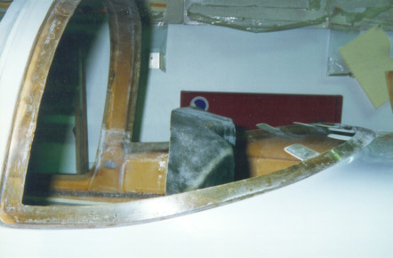
ib-2053
Window, Glasair
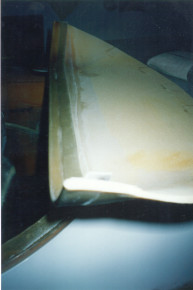
ib-2054
Glasair
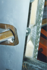
ib-2055
Glasair
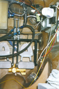
ib-2056
Glasair
ib-2057
Glasair
Glasair Jump-Start Wing and Fuse
Detail photo of the Glasair Jump-Start Wing and Fuselage options - Glasair Super II, Wing, Fuselage, Glasair
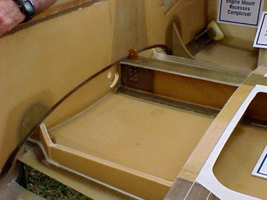
Glasair Jump-Start Wing and Fuse
Detail photo of the Glasair Jump-Start Wing and Fuselage options - Glasair Super II, Wing, Fuselage, Glasair
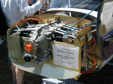
Arlington Glasair / GlaStar Booth
Firewall forward kit being developed for the GlaStar using the XP-360 engine. Word was that after the GlaStar FWF kit is developed, there could be a similar option for the Glasair. - Glasair, Engine, Firewall
Laminating
How to get to those hard to reach places - Glasair
Laminating
How to reach those hard to get to places - Glasair
Laminating
How to reach those hard to get to places of course the cloth is wetted with resin before you get to this stage. - Glasair
Laminating
How to reach those hard to get to places of course the cloth is wetted with resin before you get to this stage. - Glasair
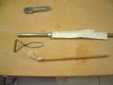
Laminating
How to reach those hard to get to places of course the cloth is wetted with resin before you get to this stage. Tools used Radiator Brush Metal Pizza style cloth cutter Metal roller 3/4 al tube - Glasair
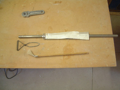
Laminating
How to reach those hard to get to places of course the cloth is wetted with resin before you get to this stage. Tools used Radiator Brush Metal Pizza style cloth cutter Metal roller 3/4 al tube - Glasair
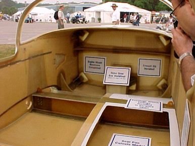
Glasair Jump-Start Wing and Fuse
Detail photo of the Glasair Jump-Start Wing and Fuselage options - Glasair Super II, Wing, Fuselage, Glasair
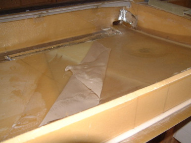
Main Aux fuel tank
Removing the peel ply after laminating two layers of cloth to the floor of the wing for the Aux fuel tanks. - Glasair, Wing, Fuel
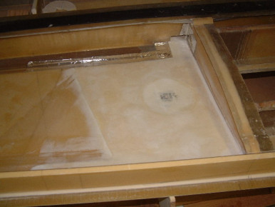
Main Aux Fuel Tank
Main Aux Fuel tank floor ready for laminating, showing dished area for additional drain point. - Glasair, Wing, Fuel
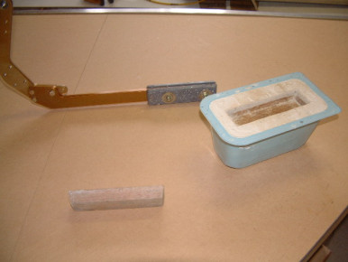
Elevators Lead Counter weight
Elevator lead counter weight mold - Glasair, Elevator
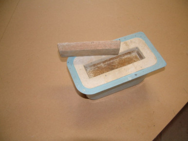
Elevators Lead Counter Weight
Elevator lead counter weight mold - Glasair, Elevator
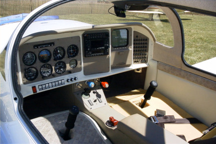
ib-2085
Panel, Glasair
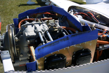
ib-2086
Engine, Glasair
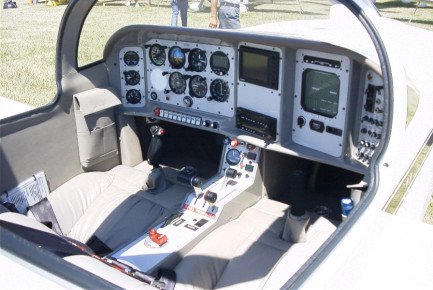
ib-2091
Panel, Glasair
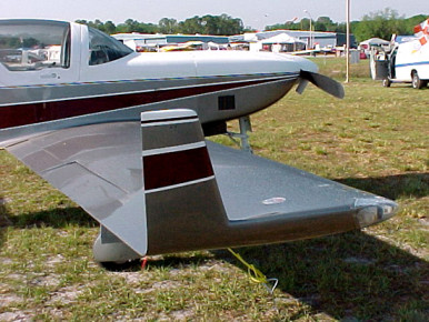
N251WH at Sun N Fun
N251WH Glasair III at Sun N Fun. A detail shot of these interesting wingtips. - Glasair III, Wing, Glasair, Wingtip
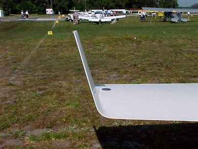
N357SS at Sun N Fun
N357SS at Sun N Fun. Detail photos of winglets. - Glasair III, Wing, Glasair
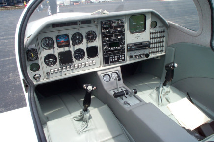
Tim Grissom's GIII
Taken during the Marysville Glasair flyin in 2001 - Glasair III, Completed, Panel, Glasair
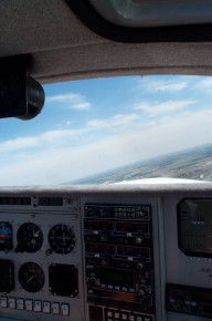
Tim Grissom's GIII
Glasair III, Completed, Panel, Glasair
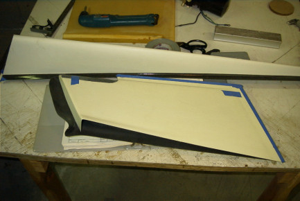
ib-2133
Glasair
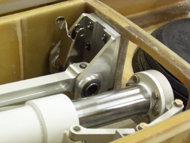
ib-2137
Gear, Glasair
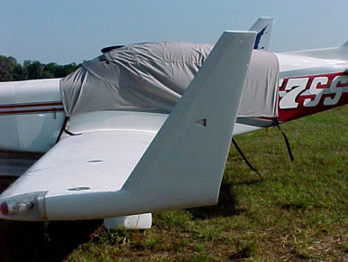
N357SS at Sun N Fun.
N357SS at Sun N Fun. Detail photos of winglets. - Glasair III, Wing, Completed, Glasair
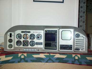
ib-2140
Panel, Glasair
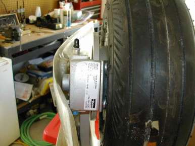
Half Fork Ramp 1
Half Fork Ramp to allow for G III brakes on a Super II RG. Steve Thomas - Glasair III, Gear, Glasair
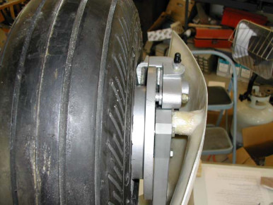
Half Fork Door 2
Half Fork Door ramp for G III brakes on a Super II RG Steve Thomas - Glasair III, Gear, Glasair
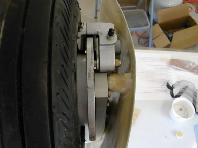
Half Fork Door 3
half Fork Door ramp for G III brakes on a Super II RG Steve Thomas - Glasair III, Wing, Glasair
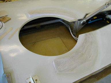
Half Fork Door 4
Half Fork Door ramp for G III brakes on a Super II RG Steve Thomas - Glasair III, Wing, Gear, Glasair
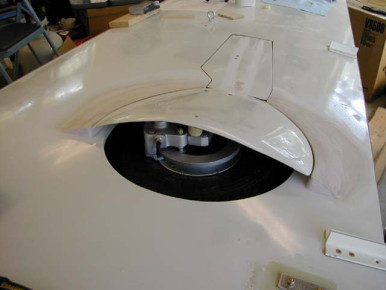
Half Fork Door 5
Half Fork Door ramp for G III brakes on a super II RG Steve Thomas - Glasair III, Wing, Gear, Glasair
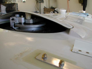
Half Fork Door 6
Half Fork Door ramp for G III brakes on a Super II RG Steve Thomas - Glasair III, Wing, Glasair
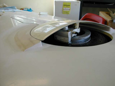
Half Fork Door 7
Hald fork door ramp for G III brakes on a Super II - Glasair III, Wing, Glasair
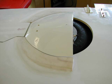
Half Fork Door 8
Half Fork Door ramp for G III brakes on a Super II RG Steve Thomas - Glasair III, Wing, Glasair
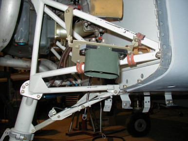
Ground power plug
I installed a standard AN power plug on the lower LH engine mount area, powering the bus through a standard continuous duty solenoid. - Glasair Super II, Engine, Glasair
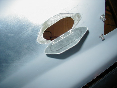
ground power door, N264X
The cowl has a camloc secured door, does not interfere with cowl removal and installation - Glasair Super II, Engine, Cowl, Glasair
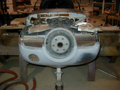
intake ramps, N264X
I fabricated the lower cowl intake areas by adding laminates over some sheet metal temporarily held in place. Its an IO360B1E in a IIS RG - Glasair Super II, Engine, Cowl, Induction, Glasair
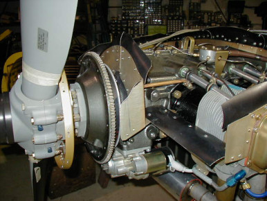
baffle detail, N264X
Here is how I closed off the front spinner/ring gear area. - Glasair Super II, Engine, Gear, Prop, Glasair
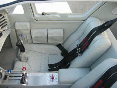
ib-2153
Seat, Interior, Glasair
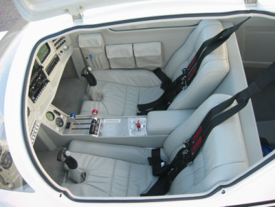
ib-2155
Panel, Glasair
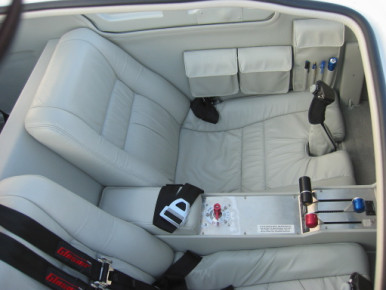
ib-2156
Seat, Interior, Glasair
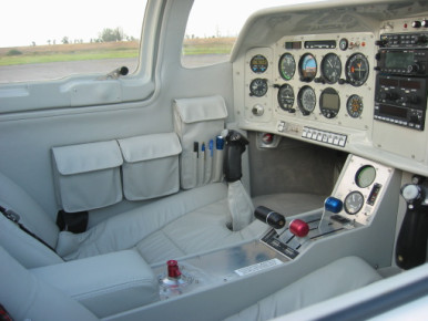
ib-2157
Panel, Glasair
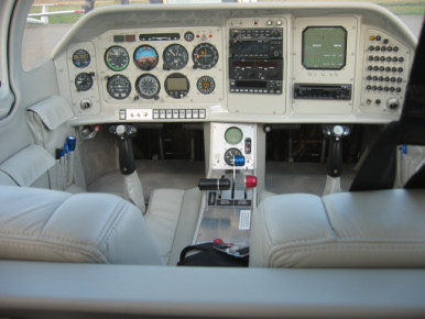
ib-2158
Panel, Glasair
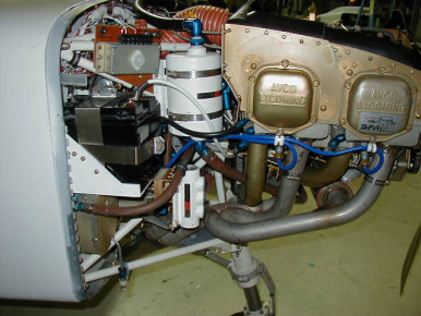
N264X engine detail
Here is a picture of my engine RH side showing the Christen system, battery and fuel strainer. Somewhat tight. - Glasair Super II, Wing, Engine, Fuel, Glasair
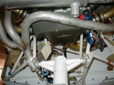
N264X engine underside
This shows the Christen sump fittings on an IO360B1E. The fittings can be clocked in any direction - Glasair Super II, Engine, Exhaust, Glasair
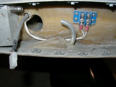
fuel vent detail
here is another picture of the flush wingtip fuel vents on my IIS RG - Glasair Super II, Wing, Fuel, Glasair
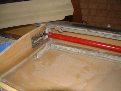
Fuel bays behind main spar
Bulkhead utilising the spar cap - Glasair, Fuel
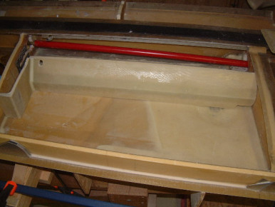
Fuel bays behind main spar
Bulkhead utilising the spar cap - Glasair, Fuel
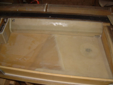
Fuel bays behind main spar
Bulkhead utilising the spar cap - Glasair, Fuel
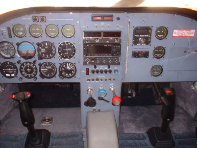
Glasair II Panel
Glasair II FT Panel on N360RB 585Hrs. TT - Glasair Super II, Panel, Glasair
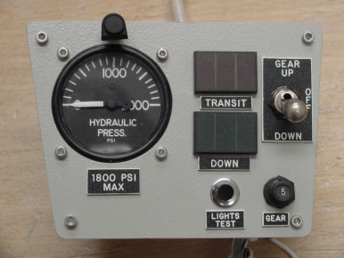
Gear control Sub Panel (center Console)
Glasair, Gear, Panel, Controls
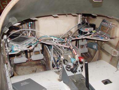
Header tank/ behind instument panel
Glasair, Panel, Fuel

Extra Conduit behind Main Spar
I installed another conduit behind the Main Spar before closing the aft fuel bays - Glasair, Wing, Fuel
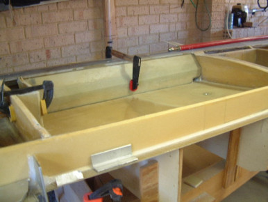
Closing Aft Fuel Bays
Closing Aft Fuel Bays behind main spar note angled bulkhead - Glasair, Fuel
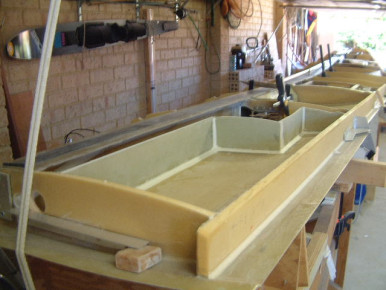
Outboard Fuel Bays
The outboard fuel bays will have their own filling point and are not connnected to the main tank. So if I am not going on a long distance flight I will not fill them - Glasair, Fuel
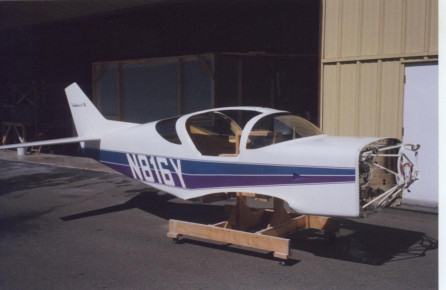
Painting in progress
I am currently painting my Super II FT. Here is the fuselage - Glasair Super II, Fuselage, Paint, Glasair
Lower Cowl Removal Cradle - 1
This cradle makes it possible for one person to remove the lower cowl without assistance. Builder Don Thompson - Glasair, Cowl
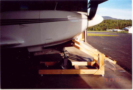
Lower Cowl Removal Cradle - 2
This cradle makes it possible for one person to remove the lower cowl without assistance. Builder: Don Thompson - Glasair, Cowl
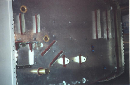
Firewall for O-360
Firewall layout for my Super II FT with O-360 engine. - Glasair Super II, Engine, Firewall, Glasair
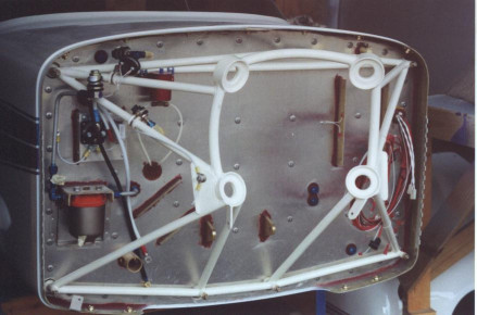
Super II-FT Firewall (O-360)
Firewall with all connections, for O-360 carbureted engine. - Glasair Super II, Engine, Firewall, Glasair
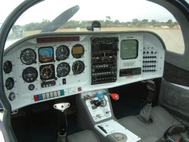
Bruce Ingham's Glasair IIS RG
This is one very nice interior - Glasair Super II, Panel, Interior, Glasair
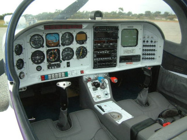
Bruce Ingham's Glasair IIS RG
A fellow buider was kind enough to bring his IIS down for me to have a look at - Glasair Super II, Interior, Panel, Glasair
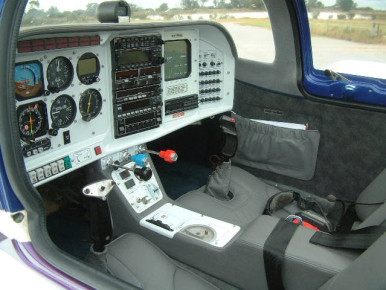
Glasair IIS RG
A fellow buider was kind enough to bring his IIS down for me to have a look at - Glasair Super II, Interior, Panel, Glasair
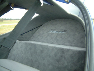
Bruce Ingham's Glasair IIS RG
very detailed baggage area - Glasair Super II, Interior, Glasair
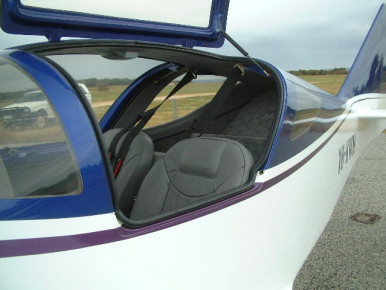
Glasair IIS RG
Very nice leather seats - Glasair Super II, Interior, Completed, Window, Fuselage, Glasair
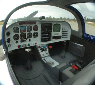
Bruce Ingham's Glasair IIS RG
This plane has the best interior that I have seen - Glasair Super II, Interior, Panel, Glasair
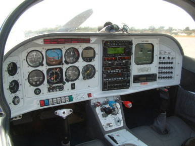
Bruce Ingham's Glasair IIS RG
This is a very nice panel - Glasair Super II, Panel, Glasair
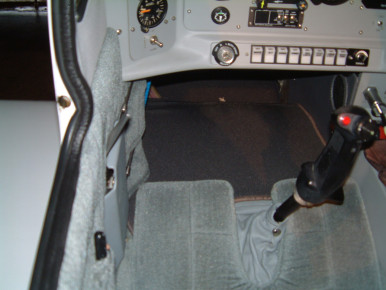
left hand throttle
Glasair, Controls, Panel
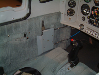
left hand throttle
Glasair, Controls
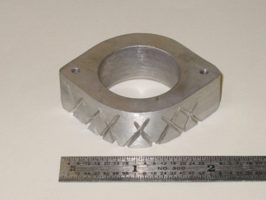
Tail Light Mounting Block
This is a tail light mounting block I made from Allen Rockwell builders hint dated 1/4/01. I fabricated it from 0.625” aluminum stock. I drilled and tapped the holes to 6-32. The grooves will aid in the milled fiber bonding of the bracket to the rudder panels. Builder: Steve Tehee - Glasair, Rudder, Fuselage, Electrical
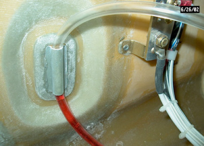
Hyd oil sight gauge
With this set-up you can see the level of the hydraulic oil during your walk-around - Glasair, Gear
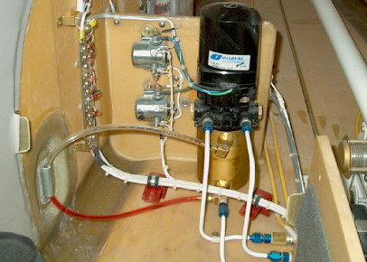
hyd oil sight gauge
Glasair, Gear
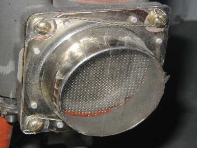
ib-2204
Glasair
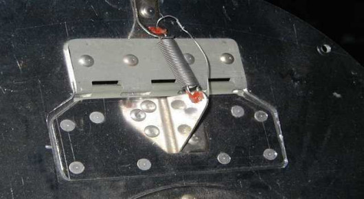
ib-2205
Glasair
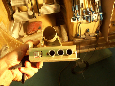
defrost fan
Took avionics fan (25 cfm) and attached hot air intake for defrost system. - Glasair, Panel, Induction
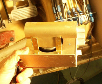
defrost fan
side view of defrost fan and warm air duct suppling warm air to inlet. - Glasair, Panel
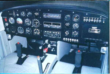
Glasair I N343ND Panel Detail
Bob Kulp's N343ND Glasair I panel detail - Glasair I, Panel, Glasair
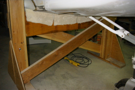
ib-2210
Glasair
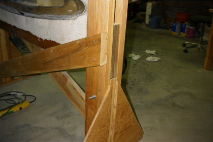
ib-2211
Glasair
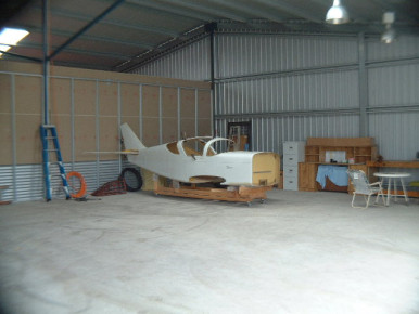
Hangar
My Glasair in it's new home it's hangar. The trolley that it is sitting on is made by cutting the wing crate in half and was very handy when I had it in my workshop at home so that I could move it out of the way when I was working on the wing. - Glasair, Wing
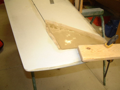
Horizontal Stab
Getting the Hor stab to match the elevators - Glasair, Elevator, Horizontal Stabilizer
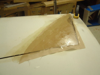
Horizontal Stab
Getting the Hor stab to match the elevators - Glasair, Elevator, Horizontal Stabilizer
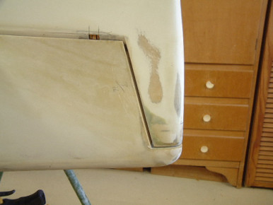
Horizontal Stab and Elevators
Getting the Hor stab to match the elevators - Glasair, Elevator, Horizontal Stabilizer
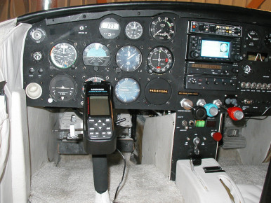
Upgraded Panel N5415 N
New PS Engineering Audio Panel, GNS 430 - Glasair, Panel
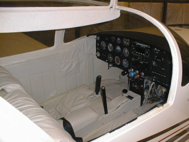
Upgraded Panel N5415 N
New PS Engineering Audio Panel, GNS 430 - Glasair, Engine, Panel
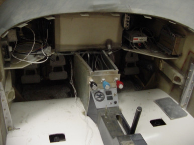
Instrument panel area
Lower center panel - Glasair, Panel
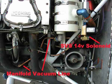
N540GL Vacuum System
Standby Vacuum System installed on Evan Julbers G III by Precise Flight of Bend, Oregon. Known for the certificated SVS units, Precise Flight installed this system in Evan's airplane to test the operation of a new 14volt electrically operated system. - Glasair III, Engine, Electrical, Glasair
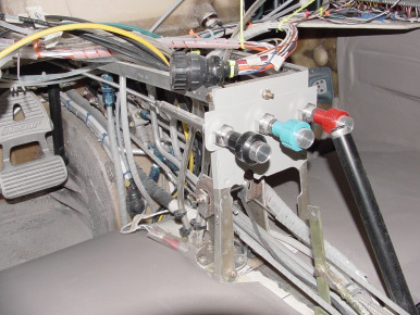
Engine Controls
Lower Center Panel - Glasair, Engine, Panel, Controls
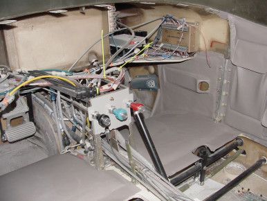
Engine Controls etc.
Lower Center panel etc - Glasair, Engine, Panel, Controls
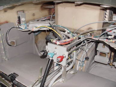
Engine Controls Etc. #2
Lower Center panel etc. - Glasair, Engine, Panel, Controls

Engine Controls
Lower Center panel close-up - Glasair, Engine, Panel, Controls
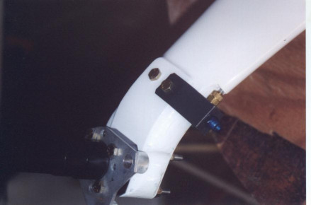
Nylaflow/hose brakeline interface on SIIFT
To avoid the problems with Nylaflow tubing softening due to brake heating in FT's, I am using a flexible heat-shielded hose within my wheelpants. Here is the interface between the nylaflow and hose. - Glasair Super II, Gear, Glasair
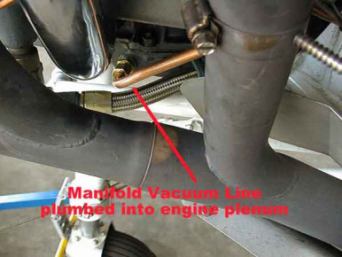
N540GL Vacuum System
Standby Vacuum System installed on Evan Julbers G III by Precise Flight of Bend, Oregon. Known for the certificated SVS units, Precise Flight installed this system in Evan's airplane to test the operation of a new 14volt electrically operated system. - Glasair III, Engine, Electrical, Exhaust, Glasair

Side brace bellcrank/spring mod 2
Glasair, Gear
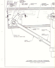
Side brace bellcrank mod 1
Glasair, Gear
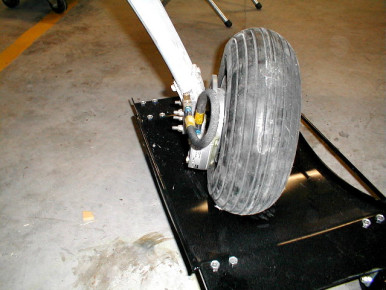
SIIS-FT Brakes
Service loop I used on my brakes. Not totally finished. I used 303 hose and AN 491 fittings. - Glasair Super II, Gear, Glasair
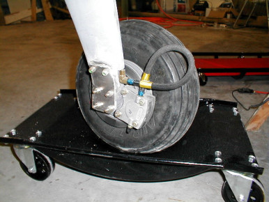
SIIS-FT brakes
Another view of the service loop separating the nylaflo from the caliper - Glasair Super II, Gear, Glasair
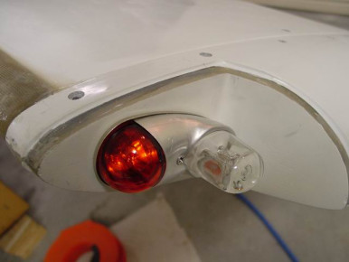
Standard tip with Whelen A650
Glasair, Wing, Electrical, Lighting
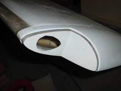
Standard tip w/ Whelen A650
Glasair, Wing
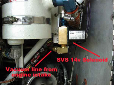
N540GL Vacuum System
Standby Vacuum System installed on Evan Julbers G III by Precise Flight of Bend, Oregon. Known for the certificated SVS units, Precise Flight installed this system in Evan's airplane to test the operation of a new 14volt electrically operated system. - Glasair III, Engine, Electrical, Glasair
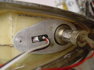
Standard tip w/ Whelen A650
Glasair, Wing
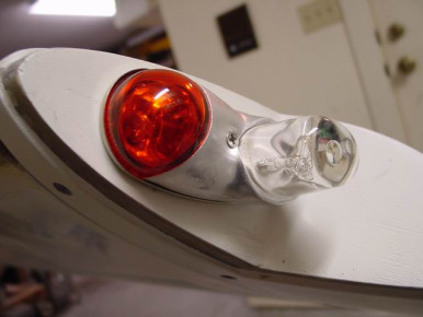
Standard tip w/ Whelen A650
The A650 will fit if you cut out an irregular shape in the bulkhead. I had to experiment w/ various shapes to find one that would allow the strobe unit to be inserted without hitting the edge of the plexiglass. It's close but it's possible. The A650 is held on by an aluminum backing plate and 2 screws. - Glasair, Wing, Electrical, Lighting
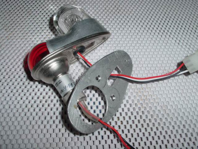
Standard tip w/ Whelen A650
Glasair, Wing, Electrical, Lighting
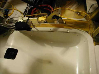
ib-2243
Seat, Wing, Glasair
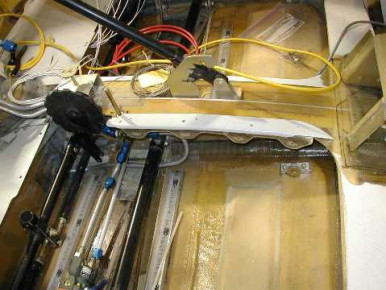
ib-2244
Seat, Wing, Glasair
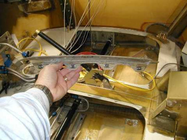
ib-2245
Seat, Wing, Glasair
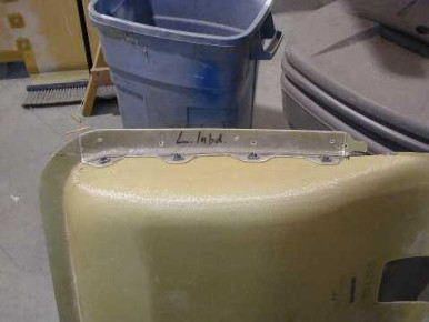
ib-2246
Seat, Wing, Glasair

Sam and Bruce Tabor
All UPS, Sandel and S-tek - Glasair, Panel
N540GL Vacuum System
Standby Vacuum System installed on Evan Julbers G III by Precise Flight of Bend, Oregon. Known for the certificated SVS units, Precise Flight installed this system in Evan's airplane to test the operation of a new 14volt electrically operated system. - Glasair III, Engine, Electrical, Glasair

Sam and Bruce Tabor
Glasair III interior - Glasair, Interior, Panel
End view of Glasair Super II wing
In this view you can see the angle that I screwed to my outer rib for spot checking my wing for level, I also have angles screwed to my fuselage, it makes leveling a lot easier - Glasair Super II, Wing, Glasair
Interior G1
here is the Interior just need to finish up a little wireing - Glasair, Panel, Interior
Interior
Glasair 1 interior - Glasair, Panel, Interior
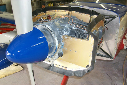
Engine Baffle
a shot of the engine - Glasair, Engine
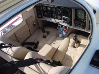
Sam and Bruce Tabor
Panel and Interior of our Glasair III - Glasair, Panel, Interior
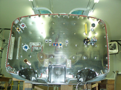
Stainless Steel Firewall and Nose wheel well
Glasair III (N8MH) finished my firewall, ready to reinstall the engine. All attached hardware will be painted carmine to match the engine. - Glasair, Engine, Paint, Firewall
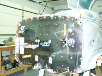
Stainless steel firewall and nose wheel well
side view of my Glasair III firewall finished - Glasair, Engine, Firewall
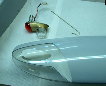
No screws installation
Wing tip lights - Glasair, Wing, Electrical, Lighting, Wingtip
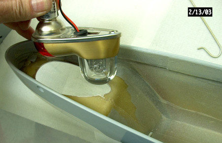
no screws
Wing tip light installation - Glasair, Wing, Electrical, Lighting, Wingtip
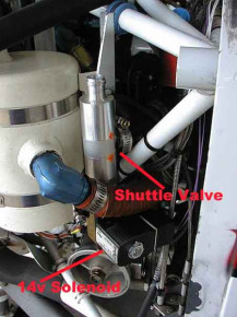
N540GL Vacuum System
Standby Vacuum System installed on Evan Julbers G III by Precise Flight of Bend, Oregon. Known for the certificated SVS units, Precise Flight installed this system in Evan's airplane to test the operation of a new 14volt electrically operated system. - Glasair III, Engine, Electrical, Glasair
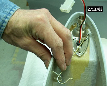
no screws
wing tip light - Glasair, Wing, Electrical, Lighting, Wingtip
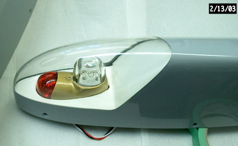
screwless
tip lights - Glasair, Wing, Electrical, Lighting
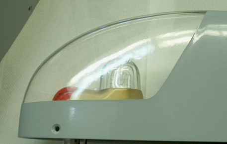
spring wire pressure
tip light - Glasair, Wing, Electrical
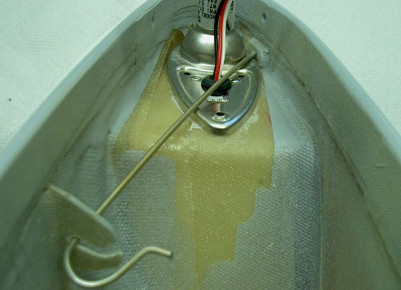
lens
tip lights - Glasair, Wing, Electrical, Lighting
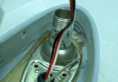
end bend
tip light - Glasair, Wing, Electrical, Lighting
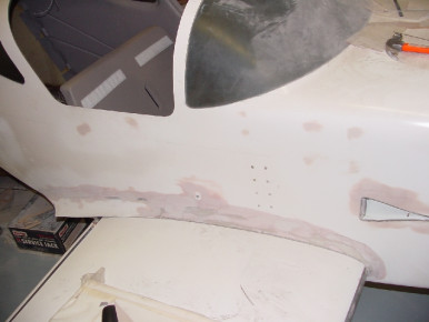
Wing to fuselage fairings
Top view, Only used back 1/3rd of factory fairings. - Glasair, Wing, Fuselage
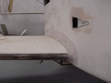
Wing to fuselage fairing
Leading edge and belly panel - Glasair, Wing, Fuselage, Panel
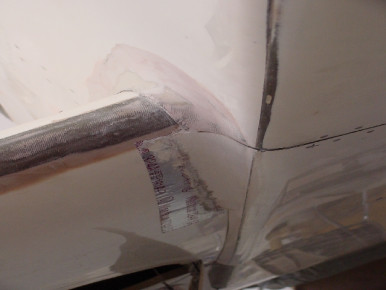
Wing to fuselage fairing
Front lower fairing to belly panel - Glasair, Wing, Fuselage, Panel
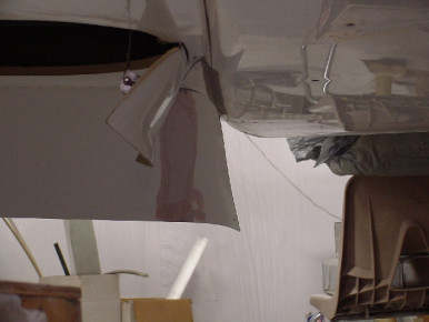
wing to Fuselage Fairing
Lower rear fairing, bonded fairing section to flap, retained flap length - Glasair, Wing, Fuselage, Flaps
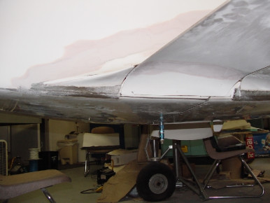
Wing to Fuselage Fairing
2nd view of fairing section bonded to flap - Glasair, Wing, Fuselage, Flaps
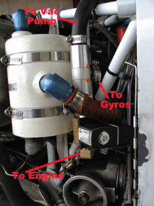
N540GL Vacuum System
Standby Vacuum System installed on Evan Julbers G III by Precise Flight of Bend, Oregon. Known for the certificated SVS units, Precise Flight installed this system in Evan's airplane to test the operation of a new 14volt electrically operated system. - Glasair III, Engine, Electrical, Glasair
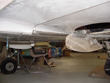
Wing to Fuselage Fairing
additional lower rear fairing section - Glasair, Wing, Fuselage
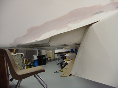
Wing to Fuselage Fairing
Flap down - Glasair, Wing, Fuselage, Flaps
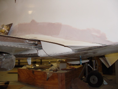
Wing to Fuselage Fairing
Flap removed oposite side - Glasair, Wing, Fuselage, Flaps
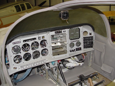
Instrument Panel etc.
Temporary installation - Glasair, Panel, Interior
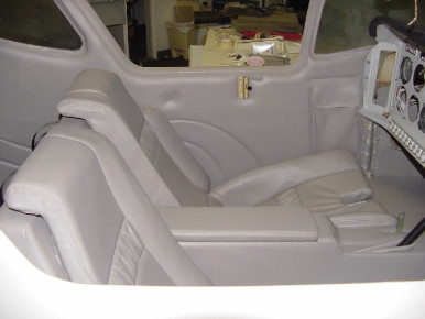
Glasair 1 Interior
Interior almost finished - Glasair, Interior, Seat
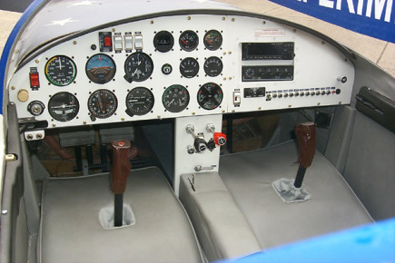
Waiting for Inspection
waiting for Inspection to finish - Glasair, Panel
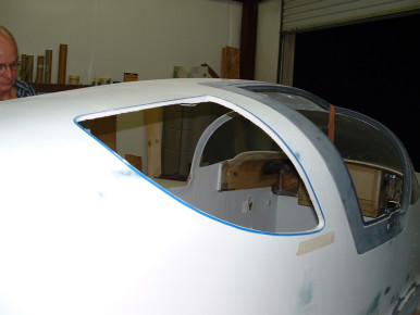
rear window
This is what it looked like after we cut out the fiber glass. - Glasair, Window, Fuselage
Fitting the nose gear strut
Fitting the nose gear strut on a Glasair Super II-s FT. Builder: Allen Rockwell - Glasair Super II, Gear, Engine, Firewall, Glasair
Steve Hammers Panel
Glasair, Panel
Instrument Panel IFR/GPS
Glasair, Panel
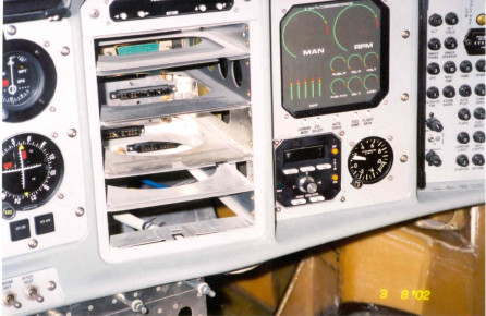
Instrument Panel IFR/GPS
This is a close up of the switches - Glasair, Panel
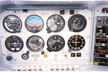
Instrument Panel IFR/GPS
Glasair, Panel
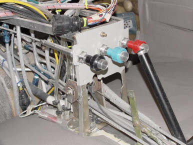
Extra rudder pulleys
Rudder pulleys at instrument panel instead of phenolic. - Glasair, Rudder, Panel, Controls
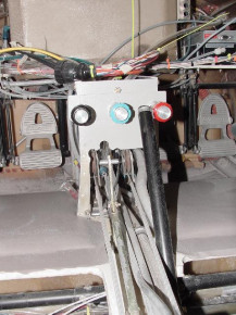
extra rudder cable pulleys
2nd view photo - Glasair, Rudder, Controls
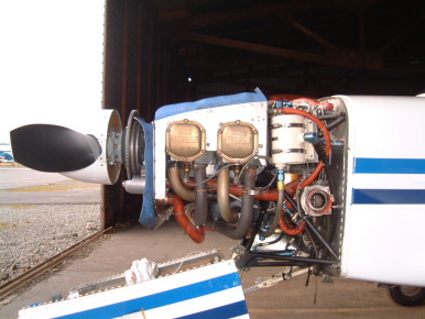
Christen air/oil separator
Glasair, Engine
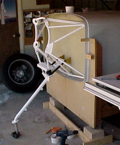
Fitting the nose gear and engine mount
Fitting the nose gear strut and engine mount to the Glasair Super II-S FT. Builder: Allen Rockwell - Glasair Super II, Engine, Gear, Glasair
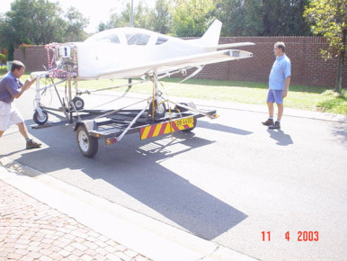
Getting the kit out of the garage
Moving your Glasair in one piece - Glasair, Moving
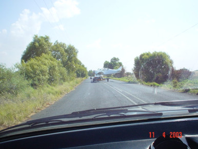
Moving your plane
On the road using a Kitfox Series 5 Trailer (slightly modified) - Moving, Glasair
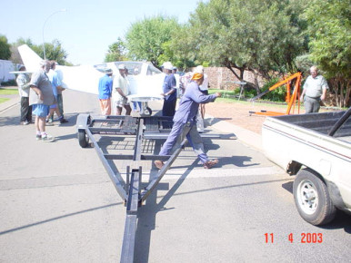
Moving your plane
Getting the aircraft onto the kitfox trailer - Moving, Glasair
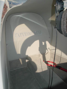
Baggage bulkhead
MV's baggage bulkhead moved aft to provide more storage area - Glasair Super II, Fuselage, Glasair
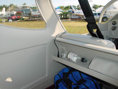
Baggage Area ledge
MV's SIIRG. Note ledge behind seat back for storage... - Glasair Super II, Interior, Glasair
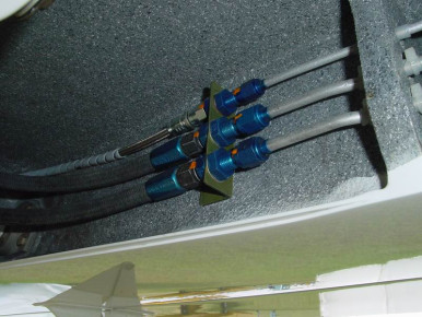
Hydraulic Connections
MV's SIIRG - Hydraulic connections in gear box - Glasair Super II, Gear, Glasair
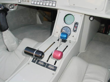
Throttle Quadrant
MV's throttle quadrant - Glasair Super II, Interior, Panel, Glasair
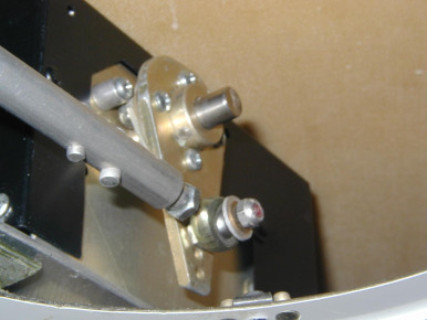
ib-2299
Controls, Glasair
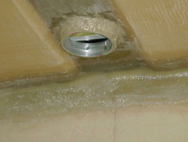
Bonding the header fuel cap
Bonding in the header tank fuel cap on the Glasiar Super II-s. View from inside the fuselage. Builder: Allen Rockwell - Glasair Super II, Fuselage, Fuel, Glasair
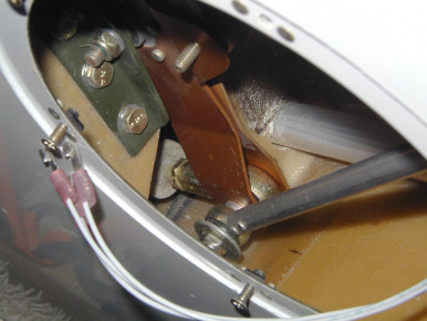
ib-2300
Controls, Glasair
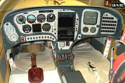
Panel
Hydraulic gauges on left - Glasair, Panel
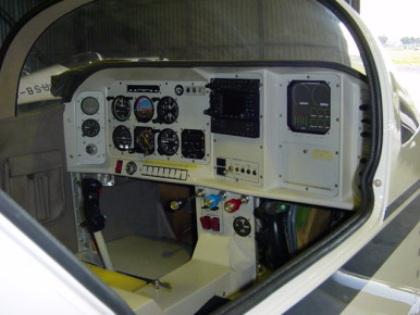
panel
Glasair, Panel
Bonding the header tank fuel cap
Bonding in the header tank fuel cap on the Glasiar Super II-s. View from outside the fuselage. Builder: Allen Rockwell - Glasair Super II, Fuselage, Fuel, Glasair
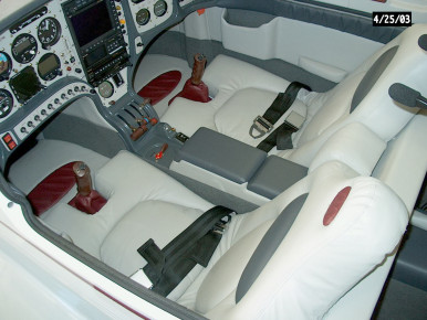
Seats
Glasair III, Completed, Panel, Interior, Seat, Glasair
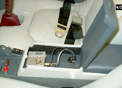
Music
Sony MD - Glasair III, Completed, Seat, Interior
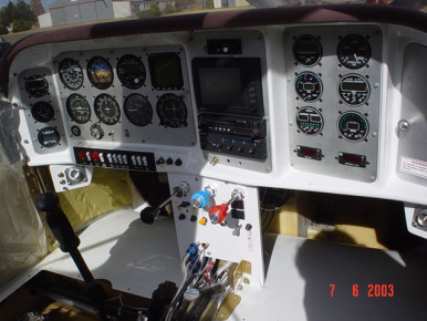
Instrument panel
Brushed aluminium finish - Glasair, Panel
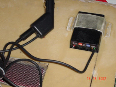
ib-2318
Panel, Glasair
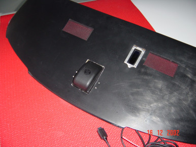
ib-2319
Panel, Glasair
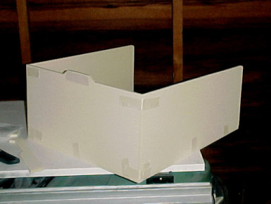
Construction of header tank
Cutting the pieces and trial fitting the header tank before laminating the foam pieces. Builder: Allen Rockwell - Glasair Super II, Fuel, Glasair
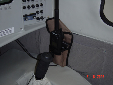
ib-2320
Panel, Glasair
ib-2321
Panel, Glasair
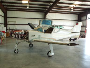
First time on wheels
Mated wing and fuselage, engine on, sitting on the gear for the first time. - Glasair, Wing, Engine, Fuselage, Gear
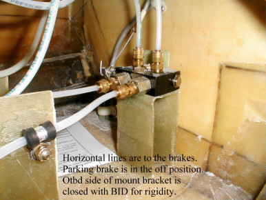
Matco parking brake
In this photo the brake is off. The mounting bracket is fwd of the left side rudder pedals but each individual installation would dictate where to mount the valve. - Glasair, Rudder, Gear
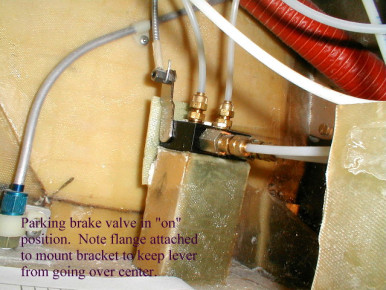
Matco parking brake Matco parking brake
In this photo the parking brake is on. I found that the Matco valve doesn't close until the rotation is very nearly 90 degrees. The control cable is a button type control cable from ACS and can be routed and cut to length to suit each individual installation. - Glasair, Gear, Controls
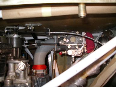
Woodward Governor
Glasair, Engine

Woodward Governor/Glasair 1 RG
Woodward governor installation on a G1 RG - Glasair, Engine
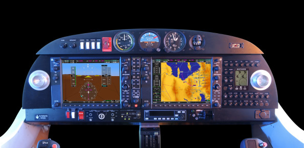
ib-2337
Panel, Glasair
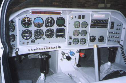
Glasair III panel
Glasair III for sale. - Glasair III, Panel, Completed, Glasair
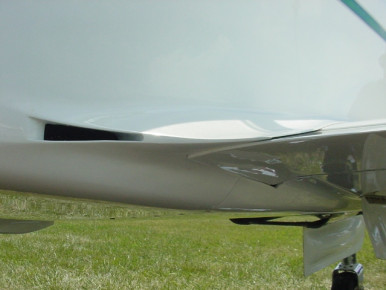
Steve Caldwell's Cabin Vent
Inside the cabin, air is drawn through a passage formed by covering the side-bottom panel recess, with an inlet just in front of the baggage bulkhead. - Glasair, Fuselage

Zolatone Paint Color Chart
Zolatone interior-canopy Paint Color Chart - Interior, Paint, Glasair
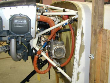
ib-2350
Engine, Glasair

ib-2351
Panel, Glasair
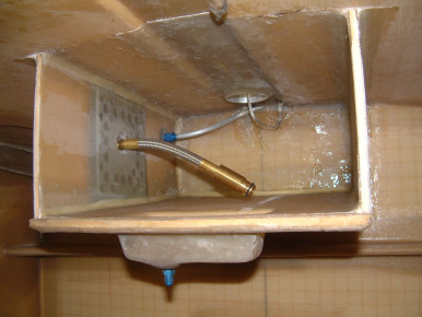
Header Tank Vent Line
This is a way of getting your header tank vent line higher in the tank. Flop tube visible. - Glasair, Fuel
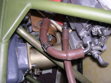
Mechanical Fuel Pump to Throttle Body
Stratoflex hose between the throttle body and mechanical fuel pump. Part number 124J012-6CR-0082 235 degrees. - Glasair, Engine, Fuel
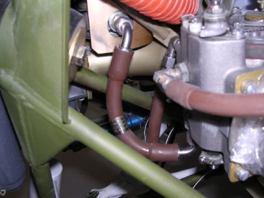
Mechanical Fuel Pump to Throttle Body
Stratoflex hose between the throttle body and mechanical fuel pump. Part number 124J012-6CR-0082 235 degrees. - Glasair, Engine, Fuel
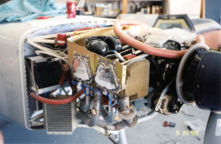
Oil Cooler installation S2 SRG
Glasair, Engine
Cowling inlet oil cooler
Glasair, Engine, Cowl
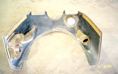
Cowling oil cooler
Glasair, Engine, Cowl
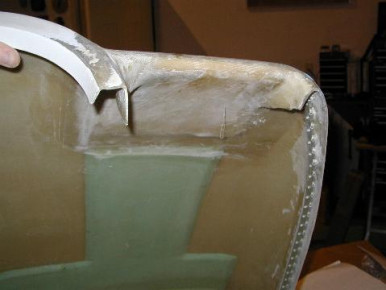
ib-2360
Cowl, Glasair
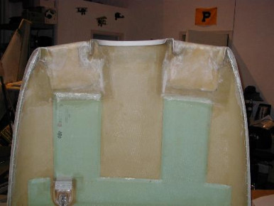
ib-2361
Cowl, Glasair
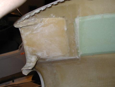
ib-2362
Glasair
ib-2363
Moving, Glasair

ib-2364
Incident, Glasair
1st start
Glasair-I N789DB started 9/19/03 on 1st crank after being pickled for 6 years. I used dessicant plugs and dried them religiously every 8-10 weeks. - Glasair, Engine
ib-2367
OLYMPUS DIGITAL CAMERA - Panel, Glasair
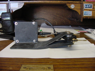
ib-2371
Glasair
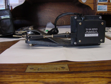
ib-2372
Glasair
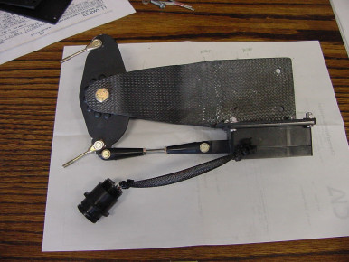
ib-2373
Glasair
ib-2374
Glasair
Super IIs RG control tunnel hydraulics
I used Aeroquip teflon hose to the underside of the manuel pump. I also moved the shunt valve up to mid console where it would be easier to find - Glasair Super II, Interior, Controls, Glasair
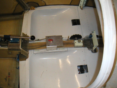
Super IIs RG
shunt valve in mid console. It will be recessed in the console and covered by a little door. Hopefully easier to find than reaching back behind the seats - Glasair Super II, Interior, Glasair
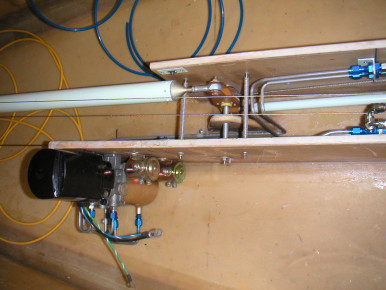
Super IIs RG hydraulic pump
hydraulic pump at the aft end of the tunnel. I hope this correct. S-H was always a little vague on how precisely to plumb this thing - Glasair Super II, Interior, Glasair
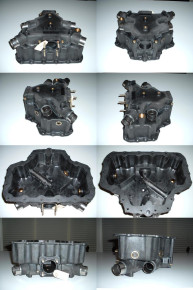
Superior Air Parts Lightweight Sump
Lightweight sump w/ cold air induction. Material is composite Ryton, weight is approx. 8 lbs. vs. 16 lbs. for Aluminium. - Glasair, Engine, Induction
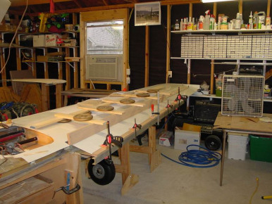
Slotted Flap closing
Glasair, Wing, Flaps
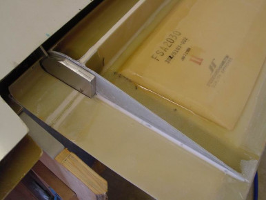
Slotted Flap inboard rib
Glasair, Wing, Flaps
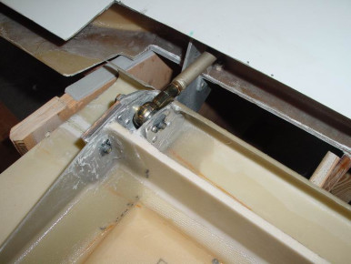
Slotted Flap inboard rib
Glasair, Wing, Flaps
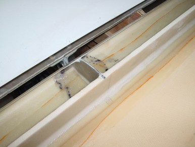
Slotted Flap center rib
Glasair, Wing, Flaps
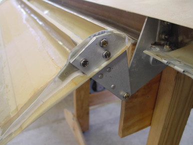
Slotted Flap Outboard Rib
Glasair, Wing, Flaps
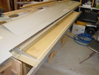
Slotted Flap Construction
Glasair, Wing, Flaps
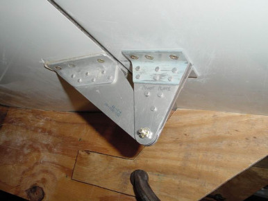
Slotted Flap center wing attach angle
Glasair, Wing, Flaps
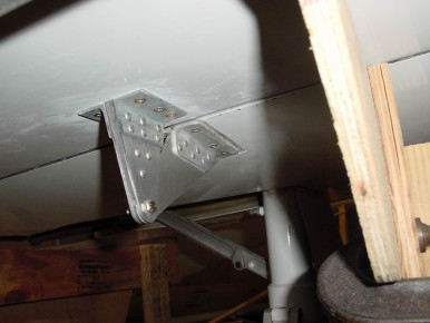
Slotted Flap Center Wing Atttach Angle
Glasair, Wing, Flaps
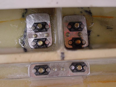
Slotted Flap Center Backplates
Glasair, Wing, Flaps
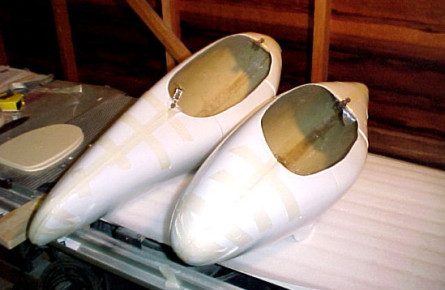
Bonding Wheel Pants
Bonding the two halves of the wheel pants together. Builder: Allen Rockwell - Glasair Super II, Gear, Glasair
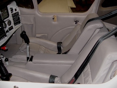
Interior GI-RG
Glasair, Interior, Seat
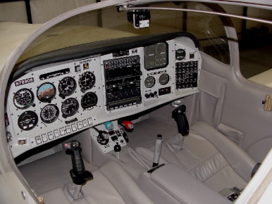
GI-RG
Glasair, Interior, Panel
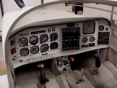
GI-RG
Glasair, Panel
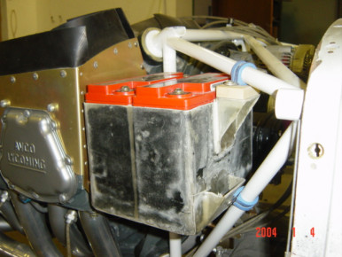
Electrical panel Z14
Glasair, Engine, Panel, Electrical
Glasair Jump-Start Fuselage
Glasair Jump-Start Fuselage - Looking at the firewall area. - Glasair Super II, Fuselage, Firewall, Glasair
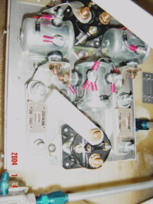
Dual Battery installation G3
Glasair, Engine
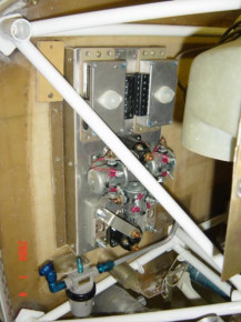
Electrical panel Z14
Glasair, Engine, Panel, Electrical
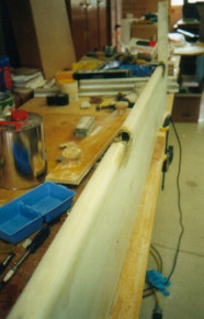
Elevators hinge finishing
Image showing gap between elevator skins filled with foam and cloth and shaped to finish - Glasair, Wing, Elevator, Horizontal Stabilizer
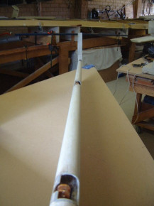
Elevator gap
Image showing gap between elevator skins filled with foam and cloth and shaped to finish - Glasair, Wing, Elevator, Horizontal Stabilizer
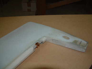
Elevators
Image showing gap between elevator skins filled with foam and cloth and shaped to finish - Glasair, Wing, Elevator, Horizontal Stabilizer
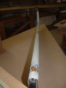
Elevators
Image showing gap between elevator skins filled with foam and cloth and shaped to finish - Glasair, Wing, Elevator, Horizontal Stabilizer
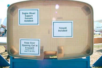
Glasair Jump-Start Fuselage
Glasair Jump-Start Fuselage - looking at the firewall forward side. - Glasair Super II, Fuselage, Firewall, Glasair
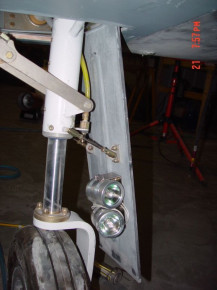
Tim Ong's Halogen Lights on Lancair Legacy
Glasair, Gear, Electrical
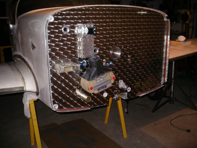
Firewall,burnished stainless steel
Glasair RG 1 with a burnished stainless steel firewall - Glasair, Fuselage, Firewall
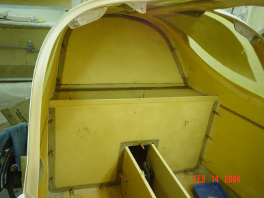
Cabin Bulkhead
Bulkhead with attaching screws on entire parameter. This is to make it airtight. (prevent cold air in CP) - Glasair, Fuselage
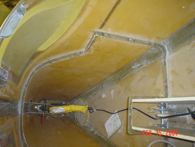
Cabin Bulkhead Mounting Bracket
Bulkhead Mounting Bracket on entire parameter. This is to make it airtight. (prevent cold air in CP) 3 Layers with 5 at the attach points. - Glasair, Fuselage
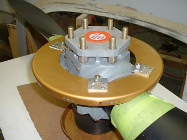
Spinner Backing Plate on New Hartzell
Spinner backplate mounted on a Hartzell Blended Airfoil Prop. - Glasair, Prop
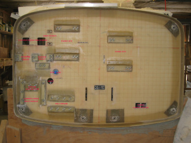
FIREWALL
I made brackets with 4 layers of bid to stand off 1/2, putting nutplates behind, then filling in with fiberfax, and enclosed it with mill fiber. the only penetrations are the AN bolts which hold everything in place and the cannon plugs. - Glasair, Engine, Firewall
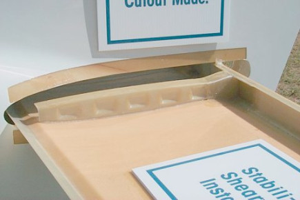
Glasair Jump-Start Stabilizer
Glasair Jump-Start Stabilizer - Glasair Super II, Horizontal Stabilizer, Glasair
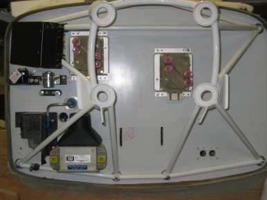
Firewall
I had to accomidate the FADEC ECUs (electronic control units) and used cannon plugs for all electrical penetrations. Heat shield and bracket supporting the relays are carbon fiber. Lory Ghertner - Glasair, Engine, Electrical, Controls, Firewall
Glasair retractable Step
Photo taken of G-III with retractable step operated by engine vacuum. - Glasair, Engine, Fuselage
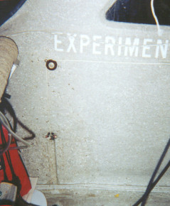
Retract step setup
Photo of G-III retract step from inside baggage. Shows tubular slide laminated to sidewall and simple rope pull to engine vacuum. - Glasair, Engine, Fuselage
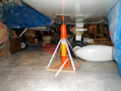
Wing jack
Jack stand I made from Harbor Freight p/n 36468-OVGA long ram jack (flat base).Plywood mount was routed in base area for base of jack. Hose clamp holding upper end of stabilizing angle is just temporary until I can get the right size muffler clamp. Cost of 3 ton jack is $39.99. Small holes will be drilled through the ram and chamfered for safety pins. - Glasair, Wing, Horizontal Stabilizer, Tools

Headsets
Headset jacks and spring loaded holder clips in overhead console - Glasair, Interior, Panel
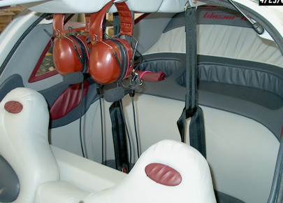
Headsets
Headsets are easy to grab and easy to stow but do get in the way when loading baggage. - Glasair, Interior

Headset jacks
I mounted my headset jacks in the top wing skin, by the side wall and just aft of the main wing attach bracket. - Glasair, Wing, Interior
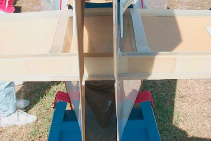
Glasair Jump-Start Stabilizer
Glasair Jump-Start Stabilizer - Glasair Super II, Horizontal Stabilizer, Glasair
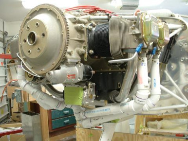
4-1 Exhaust
Plastic mockup for a 4 into 1 exhaust for an FT. - Glasair, Engine
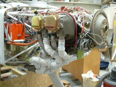
4-1 Exhaust
Plastic mockup for a 4 into 1 exhaust for an FT. - Glasair, Engine

4-1 Exhaust
Plastic mockup for a 4 into 1 exhaust for an FT. - Glasair, Engine
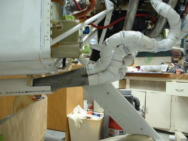
ib-2435
Engine, Exhaust, Glasair
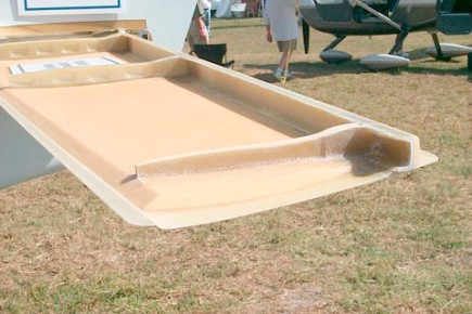
Glasair Jump-Start Stabilizer
Glasair Jump-Start Stabilizer - Glasair Super II, Horizontal Stabilizer, Glasair
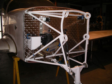
Glasair 1 RG Firewall
Burnished stainless steel firewall - Glasair, Fuselage, Firewall
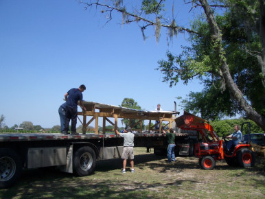
Glasair III
Being sent home to P.E.I. Canada - Glasair III, Moving, Glasair
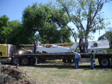
Glasair III
Fuselage added to the load. Shipping from Lakeland Fl to Charlottetown, PEI, Canada - Glasair III, Fuselage, Moving, Glasair
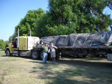
Glasair III
Loaded and on it,s way to P.E.I. - Glasair III, Moving, Glasair
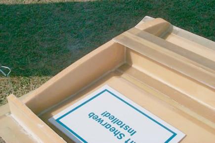
Glasair Jump-Start Wing
Glasair Jump-Start Wing - Tip area detail - Glasair Super II, Wing, Glasair, Wingtip
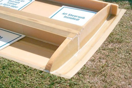
Glasair Jump-Start Wing
Glasair Jump-Start Wing - Wing tip area detail - Glasair Super II, Wing, Glasair, Wingtip
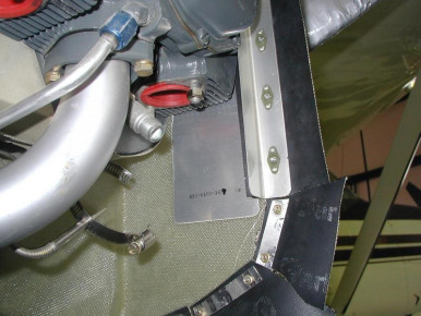
ib-2462
Engine, Exhaust, Glasair
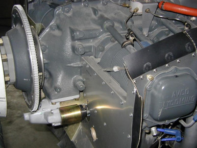
ib-2463
Engine, Glasair

ib-2465
Engine, Prop, Glasair
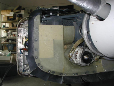
ib-2467
Engine, Glasair
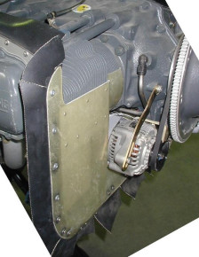
ib-2468
Engine, Glasair
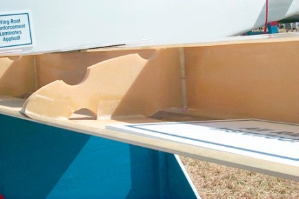
Glasair Jump-Start Wing
Glasair Jump-Start Wing - Forward rib and fuel cell baffle detail - Glasair Super II, Wing, Fuel, Glasair
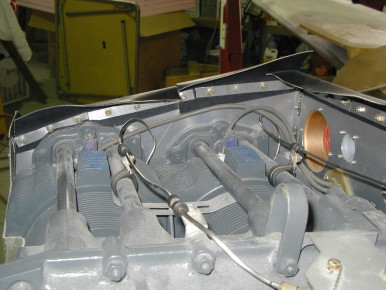
ib-2470
Engine, Glasair
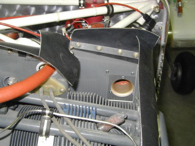
ib-2471
Engine, Glasair
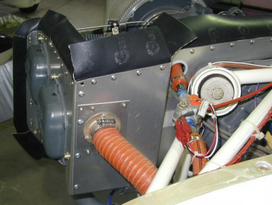
ib-2472
Engine, Glasair
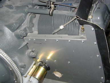
ib-2473
Engine, Glasair
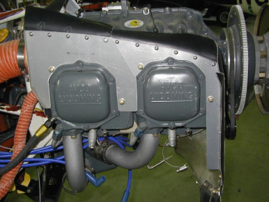
ib-2474
Engine, Glasair
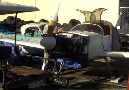
ib-2476
Glasair, Engine, Prop
Cowl attach
Blurry photo of my hinge pin cowl attach arrangement - Glasair, Cowl
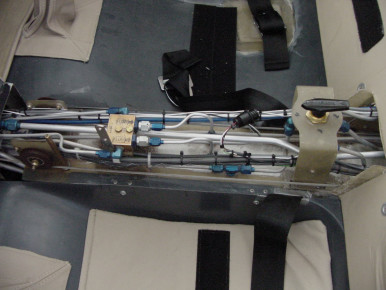
parking brake
Glasair, Controls
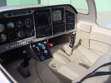
parking brake
The parking brake instillation also provides a stop for the fuel selector. Shown in the off position. - Glasair, Fuel, Controls, Panel, Interior, Seat
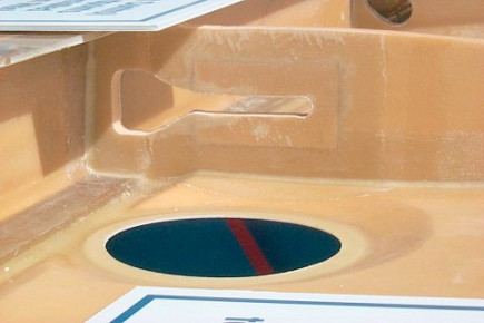
Glasair Jump-Start Wing
Glasair Jump-Start Wing - Access hole and linkage slot detail - Glasair Super II, Wing, Glasair
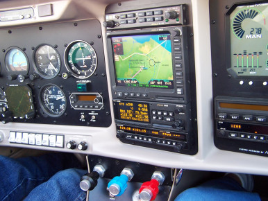
The MX 20 in action
Departing SMX for CMA - Glasair, Panel
ib-2481
Glasair
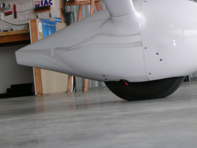
RV wheel pants airflow
This is a photo of RV wheel pants on a Super IIFT and the airflow distribution caused by dirt when flying in the rain. - Glasair, Gear
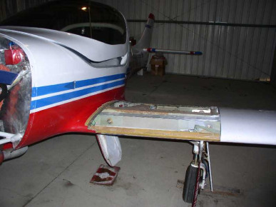
ib-2485
Wing, Gear, Fuselage, Glasair
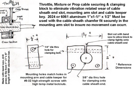
Throttle/Prop/Mixt Cable Keeper Clamp
Simple clamp to rigidly secure the cable sheath end to the slotted mounting bracket. This will eliminate the wear associated with vibration of the unclamped cable sheath end in the slotted bracket. Without this, the throttle cable had worn through 80% of the slotted SS bracket and the SS keeper. - Glasair, Engine, Prop
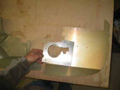
engine baffles
Since I couldn't figure out how to make the baffles fit around the starter, I did it the hard way. I removed enough material so that the front baffle could slide in behind the starter and made a starter baffle over the opening. Lory Ghertner - Glasair, Engine
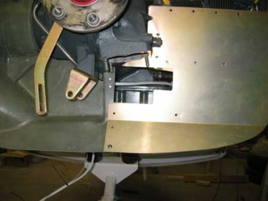
engine baffles
Glasair, Engine
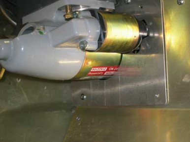
engine baffles
Glasair, Engine
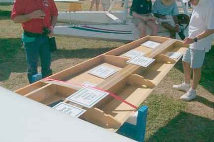
Glasair Jump-Start Wing
Glasair Jump-Start Wing - Glasair Super II, Wing, Glasair
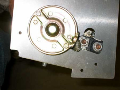
engine baffles
Glasair, Engine
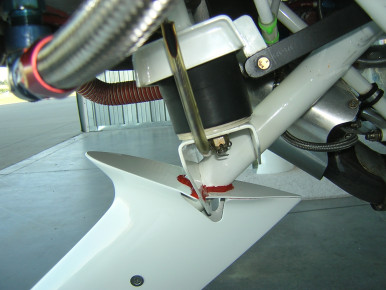
Nose wheel fairing oil shield
This is the cover/shield that I made to keep oil off the friction pad at the nose wheel fork of my Super IIFT. Have had it on sinse May and have not had a drop get throught yet. - Glasair, Gear
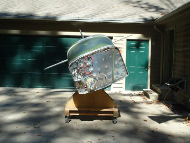
Fuselage Paint Fixture
This fixture lets me roll the fuselage about 35 degrees to each side,easing prep & painting. It consists of two posts on a 44 x 72 rolling frame, and plywood bulkheads fastened to each of the wing attach points. The posts are drilled 56 above the shop floor for a 1/2 pivot bolt, and the bulkheads are drilled 3 above WL100, which is about the level of the door pin sockets. This appears to be close enough to the vertical CG that the fuselage will stay in any position without bracing or undue friction. The rear attach point is near the longitudinal CG, so the posts are offset forward on the rolling frame. Plywood cradles fit the same frame to more securely hold the fuselage for transport & with the engine attached. With these dimensions the top of the tail is 91 above the floor. The height above the floor was chosen by judgment of the painter to provide access for spraying the paint. When rotated so that the horizontal & fin tips are the same height, it would clear an 86 door. At full lean, the fin will just clear my 83 door, so I can push it through the door until the horizontal is outside, and then roll it to one side to clear the fin. - Glasair, Wing, Engine, Fuselage, Paint, Horizontal Stabilizer, Moving
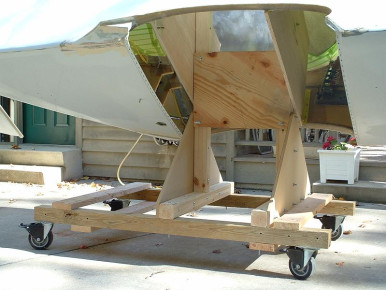
Fuselage Paint Fixture
This fixture lets me roll the fuselage about 35 degrees to each side,easing prep & painting. It consists of two posts on a 44 x 72 rolling frame, and plywood bulkheads fastened to each of the wing attach points. The posts are drilled 56 above the shop floor for a 1/2 pivot bolt, and the bulkheads are drilled 3 above WL100, which is about the level of the door pin sockets. This appears to be close enough to the vertical CG that the fuselage will stay in any position without bracing or undue friction. The rear attach point is near the longitudinal CG, so the posts are offset forward on the rolling frame. Plywood cradles fit the same frame to more securely hold the fuselage for transport & with the engine attached. With these dimensions the top of the tail is 91 above the floor. The height above the floor was chosen by judgment of the painter to provide access for spraying the paint. When rotated so that the horizontal & fin tips are the same height, it would clear an 86 door. At full lean, the fin will just clear my 83 door, so I can push it through the door until the horizontal is outside, and then roll it to one side to clear the fin. - Glasair, Wing, Fuselage, Paint, Horizontal Stabilizer, Tools, Moving
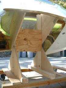
Fuselage Paint Fixture
This fixture lets me roll the fuselage about 35 degrees to each side,easing prep & painting. It consists of two posts on a 44 x 72 rolling frame, and plywood bulkheads fastened to each of the wing attach points. The posts are drilled 56 above the shop floor for a 1/2 pivot bolt, and the bulkheads are drilled 3 above WL100, which is about the level of the door pin sockets. This appears to be close enough to the vertical CG that the fuselage will stay in any position without bracing or undue friction. The rear attach point is near the longitudinal CG, so the posts are offset forward on the rolling frame. Plywood cradles fit the same frame to more securely hold the fuselage for transport & with the engine attached. With these dimensions the top of the tail is 91 above the floor. The height above the floor was chosen by judgment of the painter to provide access for spraying the paint. When rotated so that the horizontal & fin tips are the same height, it would clear an 86 door. At full lean, the fin will just clear my 83 door, so I can push it through the door until the horizontal is outside, and then roll it to one side to clear the fin. - Glasair, Wing, Engine, Fuselage, Paint, Horizontal Stabilizer, Moving
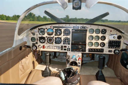
N333KM
Glasair, Panel
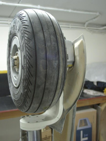
Gear Door detail
Glasair, Gear
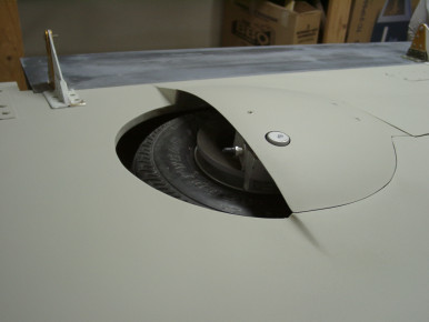
Gear Door detail
Glasair, Gear
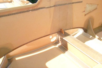
Glasair Jump-Start Wing and Fuse
Glasair Jump-Start Wing and FuseLAGE - Glasair Super II, Wing, Fuselage, Glasair
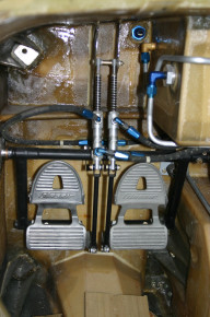
Glasair rudder pedals
shows hookup of Glasair 3 rudder pedals - Glasair, Rudder, Controls
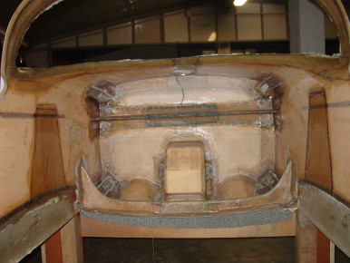
Firewall from inside
firewall with engine mount, fuel cap installed. GIII serial nr. 3317 diego trevisan italy - Glasair, Engine, Fuselage, Fuel, Firewall
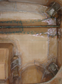
Firewall from inside
firewall with engine mount, fuel cap installed. GIII serial nr. 3317 diego trevisan italy - Glasair, Engine, Fuselage, Fuel, Firewall
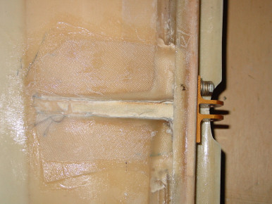
elevator
elavator rib GIII 3317 Diego Trevisan Italy - Glasair, Elevator
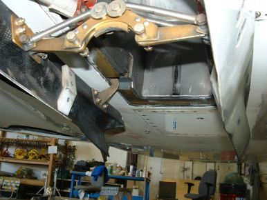
Glasair III nose gear doors
good picture showing nose gear doors, hinges and retract mechanisim. - Glasair III, Wing, Gear, Glasair
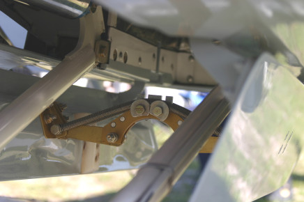
Nose gear Glasair 3
Picture showing Glasair 3 nose gear retract mechanisim - Glasair, Wing, Gear
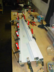
Elevator
Glasair, Elevator, Horizontal Stabilizer
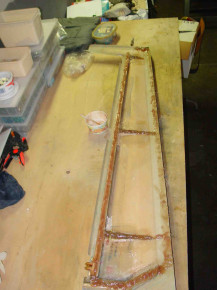
Elevator
Glasair III Trevisan Diego - Glasair, Elevator, Horizontal Stabilizer
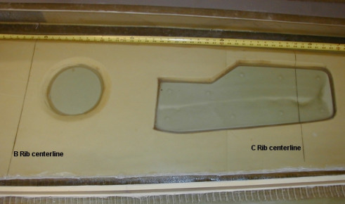
landing gear cut out
Area between B and C ribs on Super IIRG - Glasair, Wing, Gear
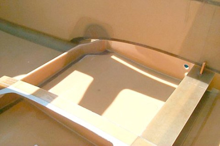
Glasair Jump-Start Wing and Fuse
Glasair Jump-Start Wing and Fuselage showing wing mount hardware. - Glasair Super II, Wing, Fuselage, Glasair
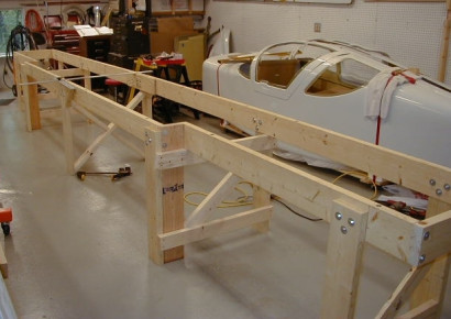
Wing Jig Frame
Wing jig for Super II Rg with wider center section to allow for clearance of landing gear while in jig. - Glasair, Wing, Gear
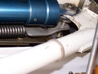
GAIII nose gear up-lock
When testing the emergency gear down system (duel actuator option ) on our GAIII we discovered that the up-lock hook would not release consistently when the up pressure was removed. The problem seemed to be low spring force and binding in the release mechanism. The binding is probably due to the mechanisms geometry which produces a large bending moment at the actuator rear attach point. If the up-lock hook is not released when the up pressure is removed, using the back up actuator on the duel actuator system will only drive the up- lock stud into the hook even harder. The included pictures are of a system designed by Dace Kirk. It is a much more robust design that works every time. - Glasair III, Gear, Glasair
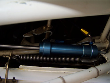
GAIII nose gear up-lock
Glasair III, Gear, Glasair
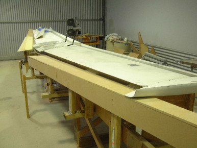
Wing Trailing edge jig
Wing Trailing edge jig - Glasair, Wing
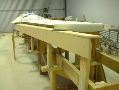
Wing Trailing edge jig
Wing Trailing edge jig - Glasair, Wing
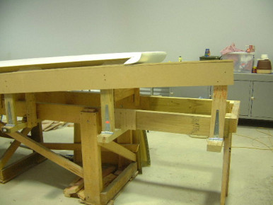
Wing Trailing edge jig
Wing Trailing edge jig - Glasair, Wing
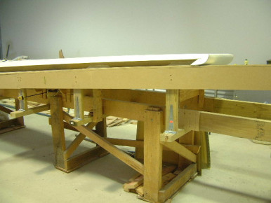
Wing Trailing edge jig
Wing Trailing edge jig - Glasair, Wing
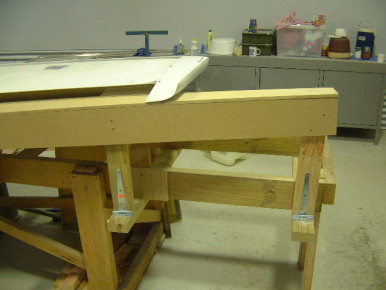
Wing Trailing edge jig
Wing Trailing edge jig - Glasair, Wing
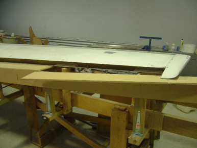
Wing Trailing edge jig
Wing Trailing edge jig - Glasair, Wing
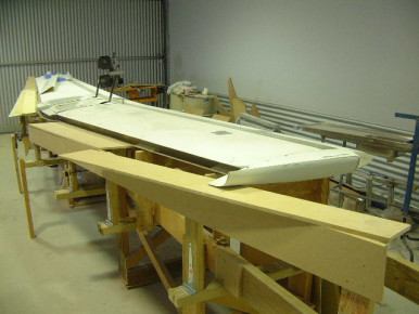
Wing Trailing edge jig
Wing Trailing edge jig - Glasair, Wing

Glasair Jump-Start Wing and Fuse
Glasair Jump-Start Wing and Fuselage showing seat pan cut-out. - Glasair Super II, Wing, Fuselage, Glasair
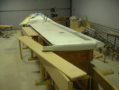
Wing Trailing edge jig
Wing Trailing edge jig - Glasair, Wing
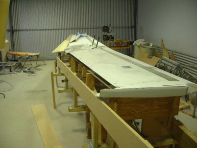
Wing Trailing edge jig
Wing Trailing edge jig - Glasair, Wing
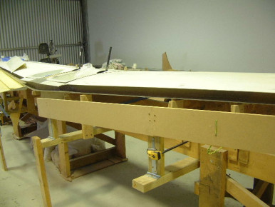
Wing Trailing edge jig
Wing Trailing edge jig - Glasair, Wing
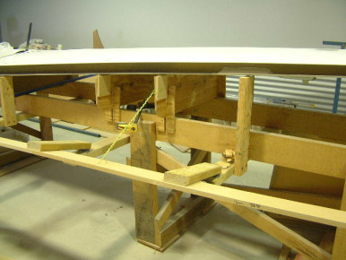
Wing Trailing edge jig
Wing Trailing edge jig - Glasair, Wing
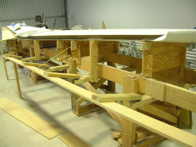
Wing Trailing edge jig
Wing Trailing edge jig - Glasair, Wing
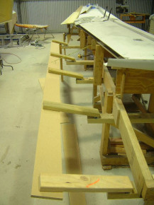
Wing Trailing edge jig
Wing Trailing edge jig - Glasair, Wing
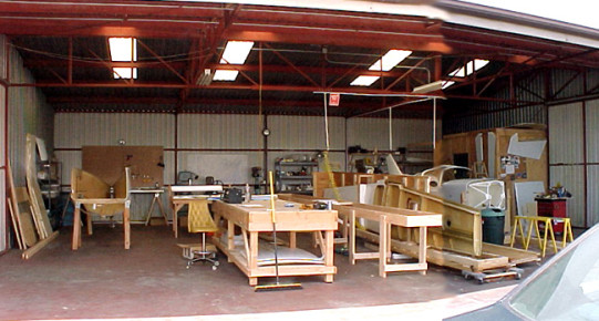
Allen Rockwell's Hangar
Two weeks after moving in to the hangar it is starting to come together. The wing will be in it's jig soon and the rest of the shipping crate plywood will be used to finish the not-so-dusty room (it's not a clean room, but it will be good enough) in the right-hand back corner where all the avionics work will take place. Allens Glasair Super II-S is the one on the right, Gregs Super II-S is the one just getting started on the left. Builders: Allen Rockwell and Greg Sadowy - Glasair Super II, Wing, Moving, Glasair
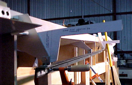
Slotted Flap Hinge Jig
Building the slotted flap hinge jig. Right wing shown. Builder: Allen Rockwell - Glasair Super II, Wing, Flaps, Glasair
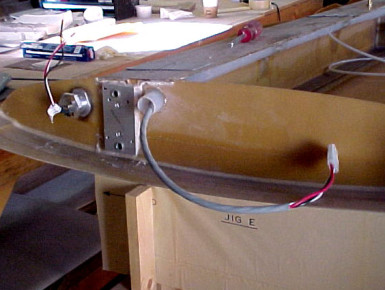
Wingtip Detail
Vision Microsystems fuel probe installed, mounting plate for fuel float valve installed and strobe wires pulled. Builder: Allen Rockwell - Glasair Super II, Wing, Fuel, Glasair
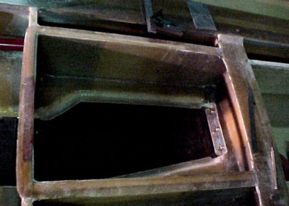
Graphite Gear Door
Graphite main gear door. Builder: Allen Rockwell - Glasair Super II, Wing, Gear, Glasair
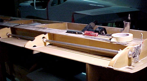
Vision Microsystems Probe In Wing
Vision Microsystems fuel level probe being installed in the wing of a Glasair Super II-s RG. Builder: Allen Rockwell - Glasair Super II, Wing, Fuel, Glasair
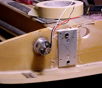
Vision Microsystems Probe In Wing
Vision Microsystems fuel level probe being installed in the wing of a Glasair Super II-s RG. Builder: Allen Rockwell - Glasair Super II, Wing, Fuel, Glasair
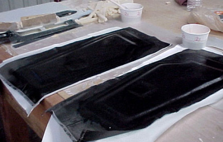
Laminating Inside of Gear Doors
Laminating the fiberglass and graphite on the inside of the main gear doors. The manual does not specify graphite here but I thought it would be a good idea to add a little stiffness here to prevent the doors from twising and possibly ripping off the plane if the gear is extended at high speed for some reason. Builder: Allen Rockwell - Glasair Super II, Gear, Glasair
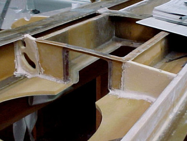
Installing The Partial C Ribs
Installing the fore and aft partial C ribs in a Glasair Super II-S RG. Builder: Allen Rockwell - Glasair Super II, Wing, Glasair
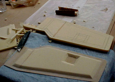
Cutting and trimming the gear doors
Cutting and trimming the foam on the Glasair Super II-S RG gear doors. Builder: Allen Rockwell. - Glasair Super II, Gear, Trim, Glasair
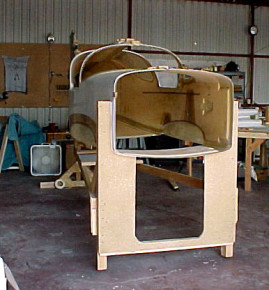
Greg Sadowy's Fuselage at 4 feet AGL
Greg Sadowy's fuselage up in its building jig. Greg built this jig a little higher off the ground than most so that he can easily get in out of the fuselage and can mount and operate his nose gear while the fuse is still in the jig. The only drawback that we've seen so far to this jig design is the possible need for a small step ladder for working on the top of the fuse and/or a small (1-2 foot tall) scaffolding type thing for working on the vertical and horiz stabs. - Glasair Super II, Fuselage, Glasair
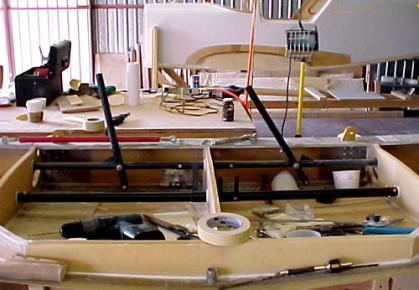
Installing Flap Torque Tubes
Installing flap torque tubes and aileron linkage in a Glasair Super II-S RG. Builder: Allen Rockwell - Glasair Super II, Flaps, Ailerons, Controls, Glasair
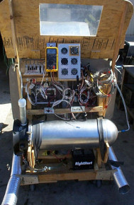
John Burnaby's Franklin Engine
Test stand detail photo. - Glasair II, Engine, Glasair
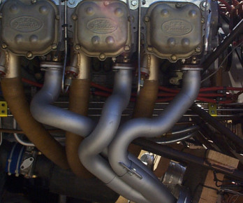
John Burnaby's Franklin Engine
Exhaust system detail - Glasair II, Engine, Exhaust, Glasair
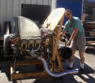
John Burnaby's Franklin Engine
Finally got my engine running on the test stand. The intake manifold is my own design and construction of Kevlar and carbon fiber. Fuel injection is Bosch KE Jetronic from a 300 E Mercedes, modified to accept manual mixture input, ignition is Lightspeed Engineering. Headers by Kenny Duttweiler, Burns Stainless provided the collectors in mild steel and Performance Coatings in WA sprayed the 2000 deg Satin Coat. Starter is a Tilton Engineering small block Chevy unit. It spins the 10.5 : 1 compression engine so fast I could probably use it to get home in an engine-out situation - Glasair II, Engine, Induction, Fuel, Glasair
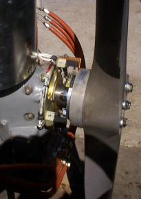
John Burnaby's Franklin Engine
LSE trigger coils, mounting plate, trigger bolt holder. After an initial problem with the mixture control design, I redesigned it and built another iteration and I am very pleased to say that everything works well. The timing needs to be dialled in for max power, but that will have to wait for flight trials. It's been a lot of work, but hearing the Franklin crackle to life and that big cam idling like a funny car brought that grin to my face - Glasair II, Engine, Controls, Glasair
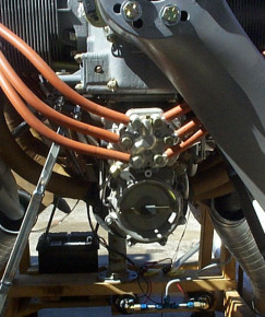
John Burnaby's Franklin Engine
Air flow sensor and fuel distributor. - Glasair II, Engine, Fuel, Glasair
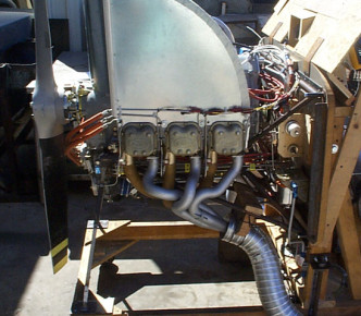
John Burnaby's Franklin Engine
Finally got my engine running on the test stand. The intake manifold is my own design and construction of Kevlar and carbon fiber. Fuel injection is Bosch KE Jetronic from a 300 E Mercedes, modified to accept manual mixture input, ignition is Lightspeed Engineering. Headers by Kenny Duttweiler, Burns Stainless provided the collectors in mild steel and Performance Coatings in WA sprayed the 2000 deg Satin Coat. Starter is a Tilton Engineering small block Chevy unit. It spins the 10.5 : 1 compression engine so fast I could probably use it to get home in an engine-out situation. - Glasair II, Engine, Induction, Fuel, Glasair
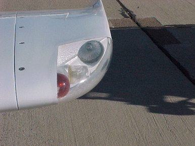
Wingtip lights on N25SX
Wingtip lights on N25SX - Glasair Super II, Wing, Electrical, Lighting, Glasair, Wingtip
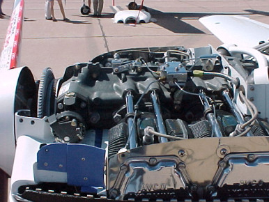
Very Nice Engine Installation
Real nice engine installation in Steven Caldwell's Glasair II RG at Copperstate 1999. Engine is a 220 hp Lycoming IO-360. - Glasair II, Engine, Glasair
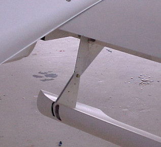
Slotted Flap Hinge Detail
Slotted flap hinge detail. Flap is dangling well below it's normal travel for this photo. Builder unknown, photo taken by Allen Rockwell at Phoenix Compostites durring Copperstate EAA Fly-In 1999. - Glasair Super II, Flaps, Ailerons, Glasair
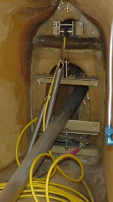
Aft Bulkhead Detail
Detail shot of the aft bulhad with elevator and rudder linkage going in. Builder unknown, photo taken by Allen Rockwell at Phoenix Compostites durring Copperstate EAA Fly-In 1999. - Glasair Super II, Rudder, Fuselage, Elevator, Glasair
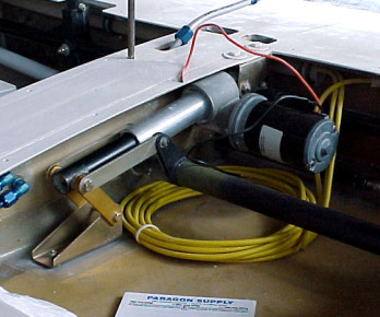
Electric Flap Installation
Electric flap instalation detail. Builder unknown, photo taken by Allen Rockwell at Phoenix Compostites durring Copperstate EAA Fly-In 1999. - Glasair Super II, Flaps, Electrical, Controls, Glasair
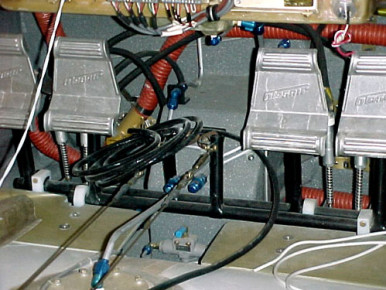
Rudder Pedals Area Detail
Detail photo of rudder pedals, plumbing and other items under the instrument panel. Builder unknown, photo taken by Allen Rockwell at Phoenix Compostites durring Copperstate EAA Fly-In 1999. - Glasair Super II, Rudder, Fuselage, Panel, Glasair
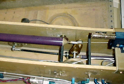
Control Tunnel Detail
Detail shot of the aft control tunnel on a Glasair Super II. Builder unknown, photo taken by Allen Rockwell at Phoenix Compostites durring Copperstate EAA Fly-In 1999. - Glasair Super II, Controls, Glasair
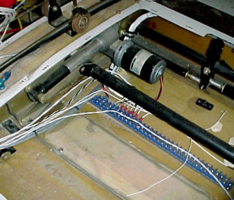
Electric Flap Installation
Detail of electric flap instalation. Builder unknown, photo taken at Phoenix Composites durring Copperstate EAA Fly-In 1999. - Glasair, Flaps, Electrical, Controls
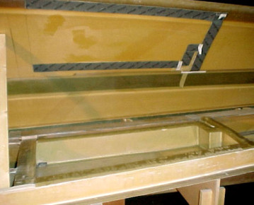
Aft Fuel Cell Flanges Applied
Aft fuel cell flanges applied. Photo taken right after opening the wing after bonding, flanges not trimmed yet. Builder: Allen Rockwell - Glasair Super II, Wing, Trim, Fuel, Glasair
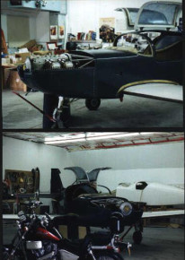
David Stoots' Glasair II-s RG
Hope to be flying this Summer(2000). Mods, IO-360 custom Lycoming 210HP with roller cam and rockers,maxi-sump intake system eletronic ignition Slotted flaps, extended wing tips w/fuel and rear fuel bays 70 gals Plus, can't have enough fuel here in Alaska. Need feed back on a good Prop to use, two or three blade. - Glasair II, Wing, Fuselage, Prop, Induction, Fuel, Flaps, Glasair
Tigger Paint Scheme
Latest version of the Tigger paint scheme that I'm considering for my Glasair Super II RG. Builder: Allen Rockwell - Glasair Super II, Paint, Glasair
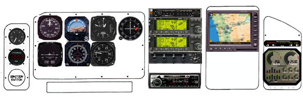
My Latest Panel Design
This is my latest panel design, 9/29/99, subject to change a million more times between now and first flight. The top GPS/COM is the primary COM, the bottom GPS/COM is used as a NAV radio and backup COM. The CDI is slaved to the bottom GPS/COM, the color multi-funtion display is driven by the top GPS/COM.
The radio under the transonder is a Sony AM/FM - MiniDisk player (CD's skip in planes, MiniDisk is a better solution). Everything in the radio stack except for the MiniDisk player is Garmin. - Panel, Glasair
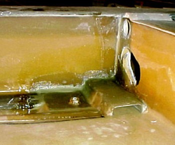
Jack Pad Installation With Aft Fuel Bay
With the aft fuel bay in a Glasair Super II you need to move the jack pad / Tie down plate outboard about 2 inches due to the fuel transfer tunnel. Builder: Allen Rockwell - Glasair Super II, Wing, Fuel, Glasair
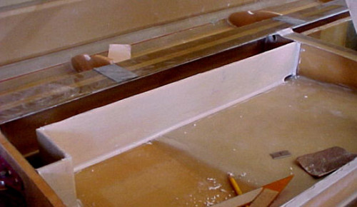
Constructing The Aft Fuel Bay
Constructing the aft fuel bay in a Glasair Super II-S RG. This fuel bay is standard on the Glasair III, but many Glasair II builders have opted for this option as well. Builder: Allen Rockwell - Glasair Super II, Fuel, Glasair
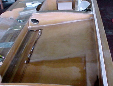
Aft Fuel Cel Laminates
Laminating over the sloped foam in the floor of the aft fuel cel. Builder: Allen Rockwell - Glasair Super II, Fuel, Glasair
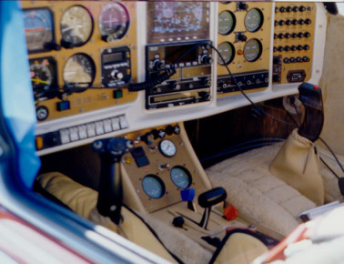
N24TX Cockpit Detail
N24TX at Jean Nevada - Glasair Super II, Panel, Glasair
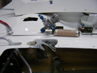
Andair extended valve installed in Rod Benson's Glasair III
Andair extended valve installed in Rod Benson's Glasair III. Base for the Andair valve was angled back to allow for the 90 degree fuel line bend from the bottom of the valve to the fuel pump. It was also angled slightly to the right to make room for the rudder cable and so the entire face plate would fit on the center console. Builder: Rod Benson - Glasair III, Rudder, Fuel, Glasair
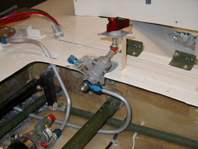
Andair Fuel Valve installed in Rod Benson's Glasair III
Andair Fuel Valve installed in Rod Benson's Glasair III. Andair valve mounted. The universal joint (expensive $60) is all that is needed to connect the valve to the selector handle. Not the special banjo fitting on the main tank fuel line connection. Builder: Rod Benson - Glasair III, Fuel, Glasair
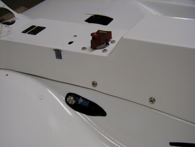
Andair fuel valve installed in Rod Benson's Glasair III
Andair fuel valve installed in Rod Benson's Glasair III. View with center console installed. The face plate is missing (being engraved). Note the modification I will need to make to the seat pan to allow room for the banjo fitting and main tank fuel line connection. Rod Benson GIII 3238 - Glasair III, Fuel, Seat, Glasair
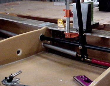
Aileron Pushrods Going In
Installing the aileron pushrods that extend from the sticks out to the bellcranks. Builder: Allen Rockwell - Glasair Super II, Ailerons, Controls, Glasair
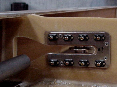
Aileron Bellcrank Bracket Nutplate Detail
Detail of the nutplates on the back side of the aileron bellcrank brackets. Builder: Allen Rockwell - Glasair Super II, Ailerons, Controls, Glasair
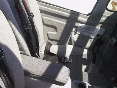
Interior Detail of N427K
Interior detail of N427K, very nice work. Photo take by Tim Shinefield at an EAA event in Longmont CO 1999. - Glasair Super II, Interior, Seat, Glasair
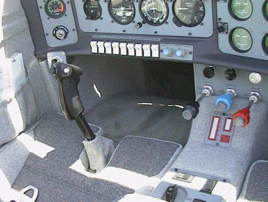
Interior Detail of N427K
Interior detail of N427K at Longmont CO. Photo by: Tim Shinefield - Glasair Super II, Interior, Panel, Glasair
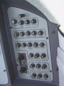
Breaker Panel on N427K
Detail of breaker panel on N427K, photo taken at Longmont CO by Tim Shinefield - Glasair Super II, Panel, Glasair
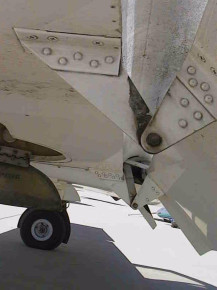
Slotted Flap Hinge Detail
Slotted flaps on Stoddard-Hamilton's demonstrator Glasari II N902S at Longmont CO. Photo by: Tim Shinefield - Glasair Super II, Flaps, Ailerons, Glasair
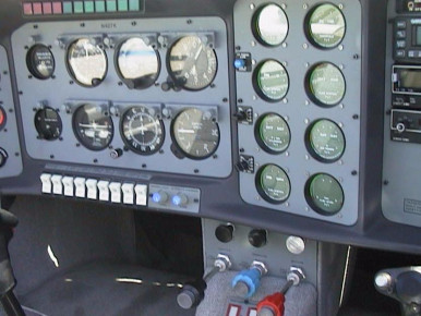
Panel in N427K
Detail of instrument panel in N427K at Longmont CO. Photo by: Tim Shinefield - Glasair Super II, Panel, Glasair
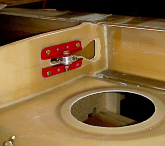
Attaching brackets for aileron bellcrank
Attaching brackets for aileron bellcrank. Builder: Allen Rockwell - Glasair Super II, Ailerons, Controls, Glasair
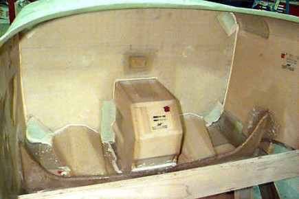
Firewall Detail Photo
Firewall and nose gear box on Greg Booher's Glasair III prior to installing rudder pedals. - Glasair III, Rudder, Fuselage, Gear, Firewall, Glasair
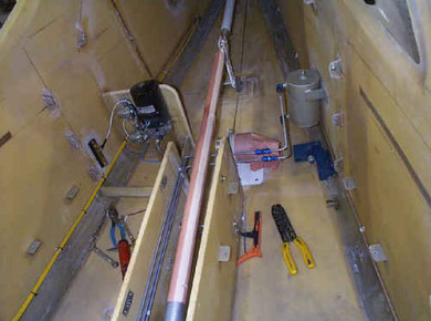
Aft Compartment Detail
Aft compartment in Greg Booher's Glasair III - Glasair III, Fuselage, Glasair
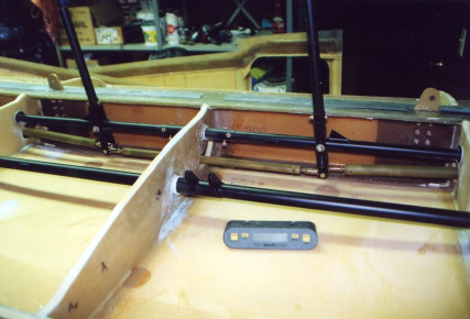
Installing The Sticks
Detail of the control sticks in Chris Yeeles' Glasair Super II-S RG. - Glasair Super II, Controls, Glasair
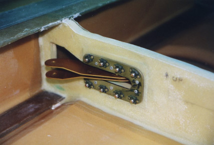
Aileron Bellcrank Detail
Detail of the aileron bellcrank. Builder: Chris Yeeles - Glasair Super II, Ailerons, Controls, Glasair
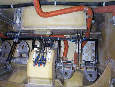
Rudder Pedals and Header Tank Detail
Nice detail shot of the rudder pedals and header tank in Greg Booher's Glasair III. - Glasair III, Rudder, Fuselage, Fuel, Interior, Glasair
Gull wing Door Installation
Greg Booher installing the gull wing doors on his Glasair III. - Glasair III, Wing, Fuselage, Glasair
Installing The Sticks
Installing the sticks and control linkage in a Glasair Super II-S RG. Builder: Allen Rockwell - Glasair Super II, Controls, Glasair
Installing The Sticks
Installing the sticks and control linkage in the Glasair Super II RG. Builder: Allen Rockwell - Glasair Super II, Controls, Glasair
Flapper Valve Installation
Flapper valve installation in the wing of a Glasair Super II. Builder: Allen Rockwell - Glasair Super II, Wing, Fuel, Flaps, Glasair
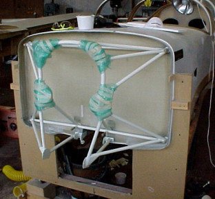
Glasair II RG Engine Mount
Mounting the Glasair Super II RG engine mount. - Glasair Super II, Engine, Fuselage, Glasair
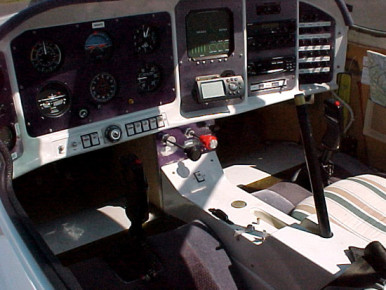
Interior Detail Of Glasair Super II-FT N884PS
Detail of interior in Glasair Super II-S FT N884PS. Nice photo showing how things go together. Builder: Paul Spainhower - Glasair Super II, Wing, Interior, Panel, Glasair
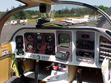
Interior Detail Of Glasair Super II-FT N884PS
Panel and interior detail of Glasair Super II-S N884PS. Builder: Paul Spainhower - Glasair Super II, Panel, Interior, Glasair
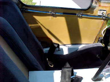
Interior Detail Of Glasair Super II-FT N884PS
Interior detail of Glasair Super II-FT N884PS still under construction. Photo taken at Orca Island WA durring the 1999 Arlington FlyIn. Builder: Paul Spainhower - Glasair Super II, Interior, Glasair
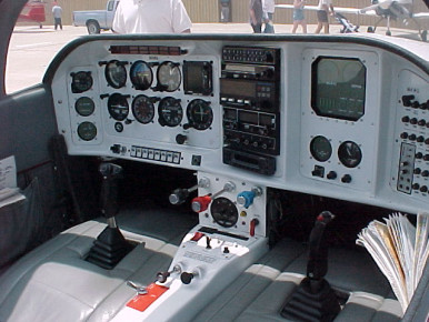
Glasair Interior and Panel Detail
Glasair Interior and Panel Detail - Glasair, Panel, Interior
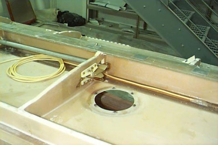
Aileron Bellcrank Installed In Wing
Aileron bellcrank installed in Greg Booher's Glasair III - Glasair III, Wing, Ailerons, Controls, Glasair
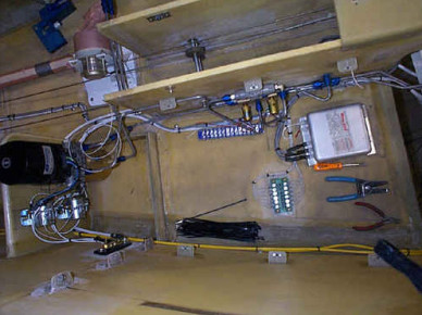
Aft Compartment Detail
Aft compartment on Greg Booher's Glasair III - Glasair III, Fuselage, Glasair
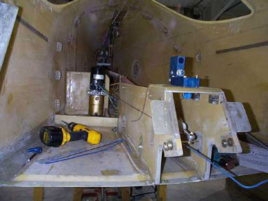
Glasair III Control Tunnel
Control tunnel on Greg Booher's Glasair III - Glasair III, Fuselage, Controls, Glasair
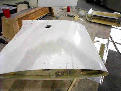
Greg Booher's Extended Wing Tips
Greg Booher's Extended Wing Tips - Glasair III, Wing, Glasair
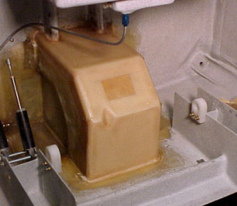
Nose Gear Wheel Well Construction
Nose gear wheel well just after laminating the exterior surfaces. Its official now, this in no longer an FT fuselage, it's an RG. Builder: Allen Rockwell - Glasair Super II, Fuselage, Gear, Glasair
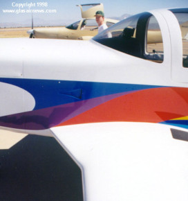
N25SX Wing Root Detail
N25SX Wing Root Detail showing the leading edge modification. - Glasair Super II, Wing, Paint, Glasair
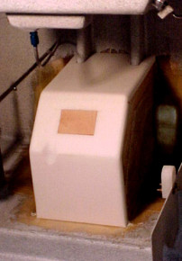
Nose Gear Wheel Well Construction
Nose gear wheel well construction on the Glasair Super II-S RG. From this angle that plywood block looks like it not straight, it's just the photo angle. Builder: Allen Rockwell - Glasair Super II, Fuselage, Gear, Glasair
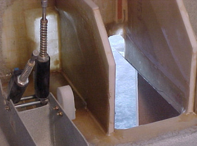
Nose Gear Wheel Well Construction
Nose gear wheel well construction on Allen Rockwell's Glasair Super II-S RG. - Glasair Super II, Fuselage, Gear, Glasair
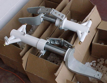
Retracts For The Glasair Super II-S
Retracts For The Glasair Super II-S - Glasair Super II, Gear, Glasair
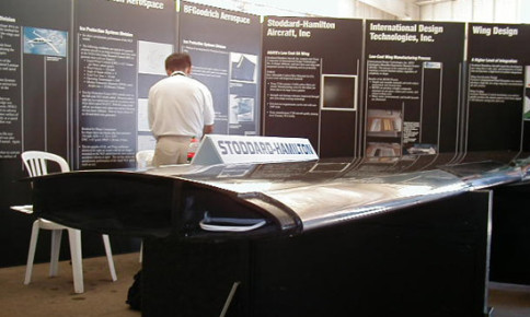
Graphite Wing For The 4-Place Glasair
Graphite wing for Glasair 4-Place on display at Oshkosh 1999 looking just as it does when it comes out of the mold. This wing panel weighs 90 lbs with the ice protection system built in. - Other, Wing, Panel, Glasair
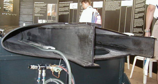
Graphite Wing For The 4-Place Glasair
Graphite wing for Glasair 4-Place on display at Oshkosh 1999 looking just as it does when it comes out of the mold. This wing panel weighs 90 lbs with the ice protection system built in. - Other, Wing, Panel, Glasair
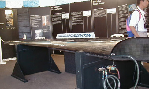
Graphite Wing For The 4-Place Glasair
Graphite wing for Glasair 4-Place on display at Oshkosh 1999 looking just as it does when it comes out of the mold. This wing panel weighs 90 lbs with the ice protection system built in. - Other, Wing, Panel, Glasair
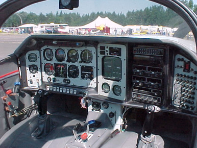
Instrument Panel in Glasair III N207GA
Instrument Panel in Glasair III N207GA - Glasair III, Panel, Glasair
N25SX Wing Root Detail
N25SX Wing Root Detail showing the trailing edge modification - Glasair Super II, Wing, Glasair
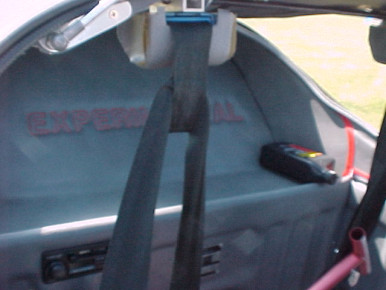
Interior Detail of Glasair III N207GA
Interior Detail of Glasair III N207GA - Glasair III, Interior, Glasair
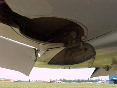
Landing Gear Door Detail
Landing gear door detail on Glasair Super II-S RG N902S - Glasair Super II, Gear, Glasair
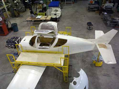
Greg Booher's Glasair III
Greg Booher's Glasair III coming along nicely. Wing attached, engine mounted and doors on. - Glasair III, Wing, Engine, Fuselage, Glasair
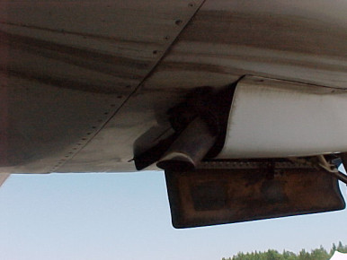
Nose Gear Door and Exhaust Detail
Nose gear door and exhaust detail on a Glasair Super II-S RG. N902S. - Glasair Super II, Gear, Glasair
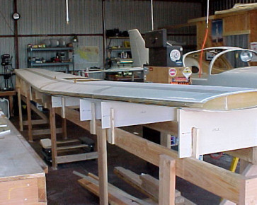
Wing Sitting In Jig
The wing jig is done and I can start work on the wing now. For anyone that is wondering, the wing jig took about 10 man-hours to build and cost about $100.00 in materials. It's built exactly as the manual suggests it be built. Builder: Allen Rockwell - Glasair Super II, Wing, Glasair
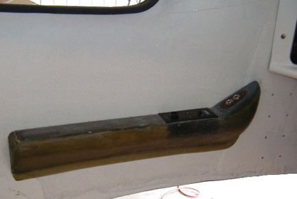
Armrests and Headset Plugs
Rod Benson's Glasair III Kit Number 3238. Armrests with Bose and regular headset connections. - Glasair III, Interior, Glasair
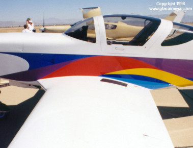
N25SX Wing Root Detail
N25SX Wing Root Detail showing LE and TE. - Glasair Super II, Wing, Paint, Glasair
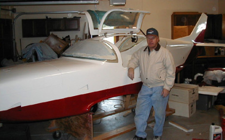
Rod Benson and His Glasair III
Rod Benson and His Glasair III kit Number 3238 - Glasair III, Fuselage, Glasair
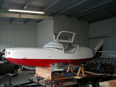
Rod Benson's Glasair III At The Hangar
Rod Benson's Glasair III Kit Number 3238. Fuselage finally at the hangar and still on the trailer. - Glasair III, Fuselage, Glasair, Moving
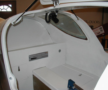
Detail of Baggage Area
Rod Benson's Glasair III Kit Number 3238 Interior rear showing mounting of Alpine 6-CD remote player, access door to hyd. pump area, and storage compartment. - Glasair III, Interior, Fuselage, Window, Glasair
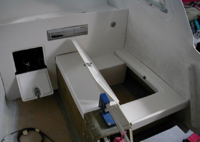
Detail of Baggage Area
Rod Benson's Glasair III Kit Number 3238. Interior rear bulkheads with compartment doors open. - Glasair III, Interior, Panel, Glasair
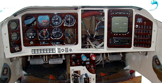
Instrument Panel in Rod Benson's Glasair III
Rod Benson's Glasair III Kit Number 3238 Instrument panel with radio stack still missing. Looks like he's putting in an Color Argus 7000 too.. Nice! - Glasair III, Panel, Glasair
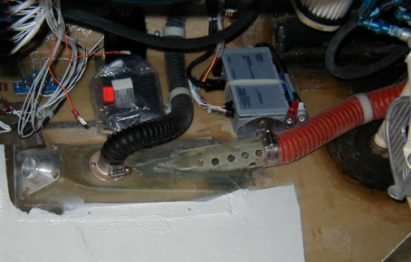
Fresh Air Inlet
Rod Bneson's Glasair III Kit Number 3238. Left fresh air outlet. The black hose connects fresh air to the right side outlet and the orange hose is from heater. The heater outlet is just mounted at that location and does not mix with the fresh air. - Glasair III, Interior, Glasair
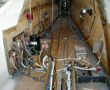
Detail Of Rear Fuselage Interior
Interior rear showing the hyd pump. The bracket on the left is for the Norstar remote transmitter. CB's are for the hot batt. buss items. Builder: Rod Benson - Glasair III, Wing, Fuselage, Interior, Glasair
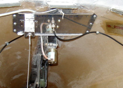
GPS and ELT Ground Plane In Rear Fuselage
Rod Benson's G-III Kit Number 3238 Interior rear showing ground plane for ELT antenna and GPS antenna. - Glasair III, Wing, Fuselage, Interior, Glasair
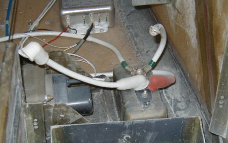
Interior Fuselage Detail - Pitch Servo, Batt Box, Power Plug
Rod Benson's GIII 3238 Interior fuselage showing pitch servo, battery box, and connections to the ground power plug. - Glasair III, Wing, Fuselage, Interior, Servo, Glasair
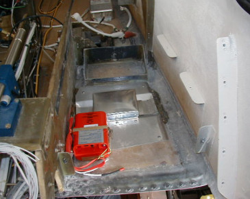
Rear Fuselage - ELT, Batt Box, Ground Plane
Rod Benson's GIII Kit Number 3238 Interior rear of fuselage showing ELT, ground plane for DME and Transponder antennas, and battery box. - Glasair III, Wing, Fuselage, Interior, Glasair
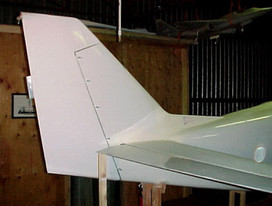
Test Fitting The Rudder And Elevators
The first photo ever of my plane with the rudder on. Test fitting the rudder and elevators. Builder: Allen Rockwell - Glasair Super II, Rudder, Elevator, Glasair
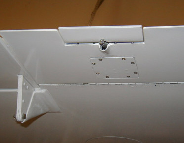
Aileron Trim On Rod Benson's Glasair III
Rod Benson's GIII 3238 Aileron trim viewed from the lower side of the wing. Also note that Rod faired in the the slotted flap hinge thereby reducing drag in that area and making it look a hell of alot nicer. - Glasair III, Wing, Trim, Flaps, Ailerons, Glasair
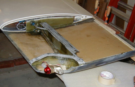
Wing Tip Extensions O n Rod Benson's G-III
Rod Benson's GIII Kit Number 3238. Wing tip extensions with fuel showing the relocated buldheads to allow for the dual nav/strobe lights. I elected to make this bulkhead out of 1/4 foam instead of just laminates. - Glasair III, Wing, Fuel, Glasair, Wingtip
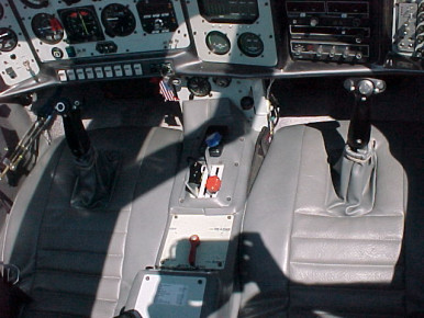
Interior Detail Of Glasair III N207GA
Interior Detail Of Glasair III N207GA at Arlington 1999 - Glasair III, Interior, Panel, Glasair
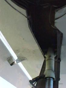
Main Gear Strut and Wheel Well Detail
Main Gear Strut and Wheel Well Detail on Glasair Super II-S RG N902S - Glasair Super II, Gear, Glasair
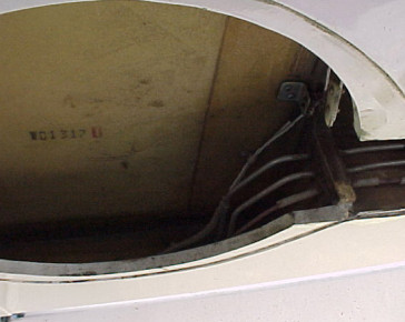
Main Gear Wheel Well
Main Gear Wheel Well on Glasair Super II-S RG N902S - Glasair Super II, Gear, Glasair
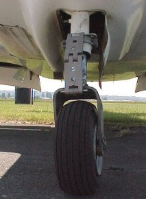
Nose Gear Detail
Nose Gear Detail on Glasair Super II-S RG N902S - Glasair Super II, Gear, Glasair
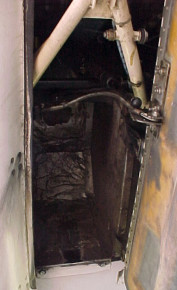
Nose Gear Wheel Well Detail
Nose Gear Wheel Well Detail on Glasair Super II-S RG N902S - Glasair Super II, Gear, Glasair
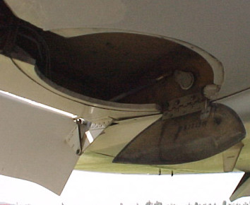
Landing Gear Door Detail
Landing Gear Door Detail on Super II-S RG N902S. - Glasair Super II, Gear, Glasair
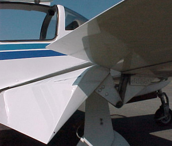
Slotted Flap Hinge Detail
Slotted Flap Hinge Detail on N902S - Glasair Super II, Flaps, Ailerons, Glasair
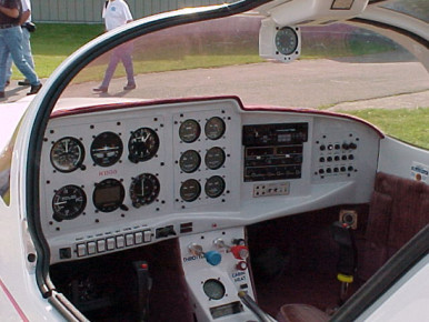
Panel In Larry Graves Glasair II-FT
Instrument Panel In Larry Graves Glasair II FT at Arlington 1999 - Glasair Super II, Panel, Glasair
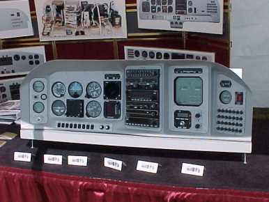
Nice Panel On Display At Arlington 1999
Nice Panel On Display At Arlington 1999 - Glasair, Panel
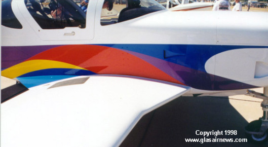
Wing mod on N25SX
N25SX at Copperstate 98 showing the wing mods done. - Glasair Super II, Wing, Completed, Paint, Glasair
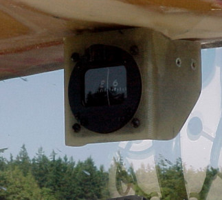
Compass Detail In Glasair Super II-FT N884PS
Compass Detail In Glasair Super II-FT N884PS. Builder: Paul Spainhower of Utah. - Glasair Super II, Interior, Glasair
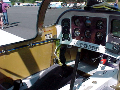
Interior Detail Of Glasair Super II-FT N884PS
Interior Detail Of Paul Spainhower's Glasair Super II-FT N884PS. Paul flew to Arlingon 1999 from Utah, his second long cross country. His first long cross country was to Sun N fun in 1999. - Glasair Super II, Interior, Panel, Glasair

Extended Wing Tip On Glasair Super II-FT N884PS
Extended Wing Tip On Paul Spainhower's Glasair Super II-FT N884PS. - Glasair Super II, Wing, Glasair, Wingtip
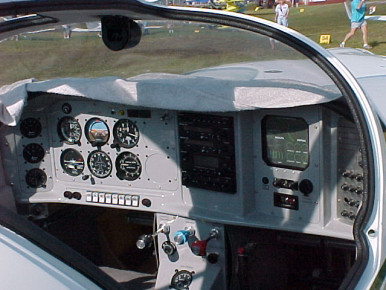
Panel in Glasair at Sun N Fun 1999
Panel in Glasair at Sun N Fun 1999 - Owner unknown - Glasair, Panel
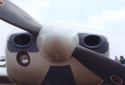
Cowl Detail of N357SS at Sun N Fun 1999
Cowl Detail of N357SS at Sun N Fun 1999 - Glasair III, Cowl, Completed, Prop, Glasair
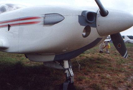
Cowl Detail of N357SS at Sun N Fun 1999
Cowl Detail of N357SS at Sun N Fun 1999 - Glasair III, Cowl, Glasair
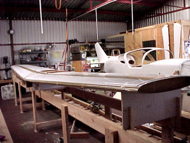
Wing Sitting In Jig
Wing Sitting In Jig. Have not installed C and D supports yet, it's just sitting in the jig. Builder: Allen Rockwell - Glasair Super II, Wing, Glasair
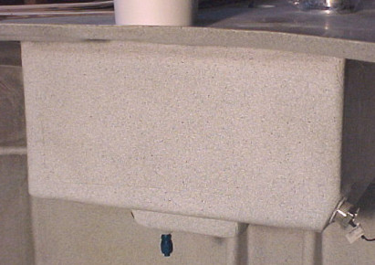
Header Tank After Paint
Header tank after an applicaiton of Zolotone cockpit paint. Builder: Allen Rockwell - Glasair Super II, Paint, Fuel, Glasair
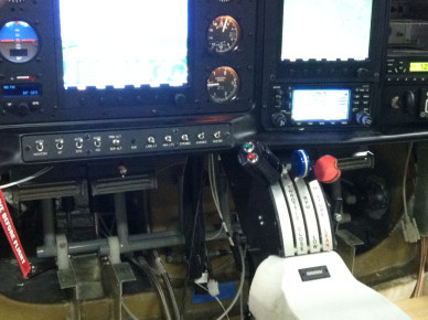
Andair Throttle Quadrant
Throttle quadrant in SII RG 69BZ - Glasair Super II, Panel, Glasair
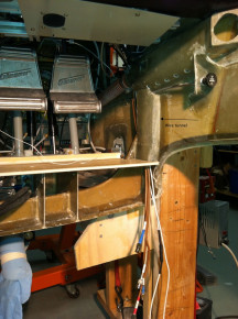
Right Side wire tunnel
I fabricated this tunnel to channel wires from behind the panel to below the wing for easy connection and to keep them out of the way. - Glasair, Wing, Electrical
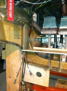
Left Side Wire Tunnel
I fabricated this tunnel to channel wires from behind the panel to below the wing for easy connection and to keep them out of the way. - Glasair, Wing, Electrical
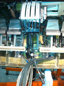
Center Console Wire and Hose Connections
I tried to limit connections in this area as much as possible but still wound up with quite a bundle - Glasair, Panel, Electrical
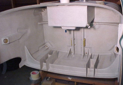
Forward Cockpit After Painting
The area forward of the instrument panel after painting with Zolotone paint. Builder: Allen Rockwell - Glasair Super II, Fuselage, Panel, Paint, Glasair
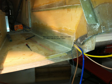
Aft Wire Tunnel
I glassed in the fuselage corners to provide a tunnel for wires coming from the tail. - Glasair, Fuselage, Electrical
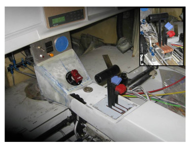
Throttle Quadrant
Throttle quandrant required some mods to make it fit with all the tubing but I think it will all workout without interfering - Glasair, Interior, Panel
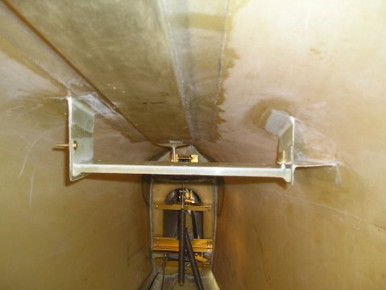
ADAHRS mounting
ADAHRS mounting tray in the rear fuselage of SIIRG. The tray is hinged at the back and the front can be moved up and down for pitch adjustment. - Glasair Super II, Fuselage, Glasair
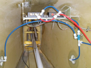
ADAHRS mounted
ADAHRS mounted above the static ports in the rear fuselage of my SIIRG . - Glasair Super II, Fuselage, Glasair
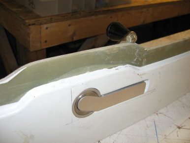
Canopy Handle Interferance
Nut contacts window plexi joggle - What to do? - Glasair, Window, Fuselage
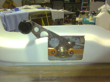
Door handle
Door handle fitted - Glasair, Fuselage, Window
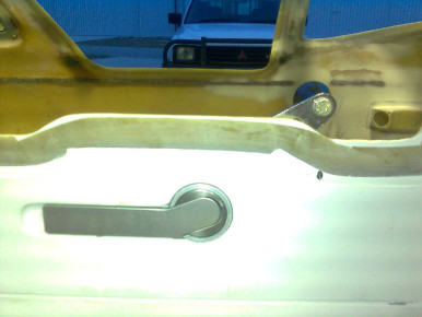
Door Handle
Door handle fitted - Glasair, Fuselage, Window
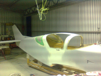
Fuselage having windows fitted
Fuselage Windows - Glasair, Window, Fuselage
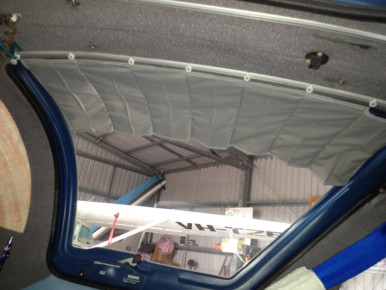
ib-3162
Window, Glasair
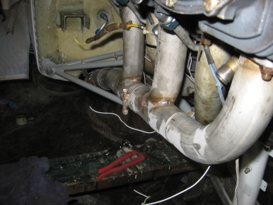
GIII Sky Dynamics Exhaust
GIII Sky Dynamics Exhaust - Installation went like a charm! www.skydynamics.com - Glasair III, Engine, Glasair
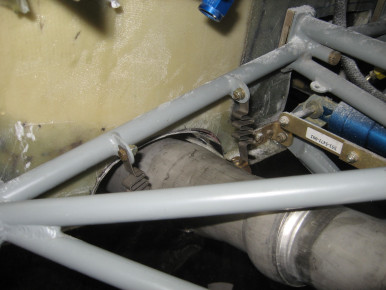
GIII Sky Dynamics Exhaust
GIII Sky Dynamics Exhaust - Installation went like a charm! www.skydynamics.com - Glasair III, Engine, Glasair
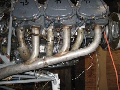
GIII Sky Dynamics Exhaust
Installation went like a charm. - Glasair III, Engine, Exhaust, Glasair
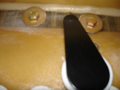
S2S FT Elec Slotted Flap Actuator arm
Super 2 S FT electric slotted flap actuator arm interference with gear mounting bracket bolt head - Glasair, Wing, Gear, Flaps, Electrical

N471B Instrument Panel
Glasair, Panel
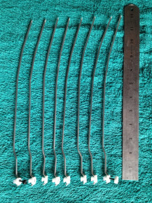
ib-3163
Glasair
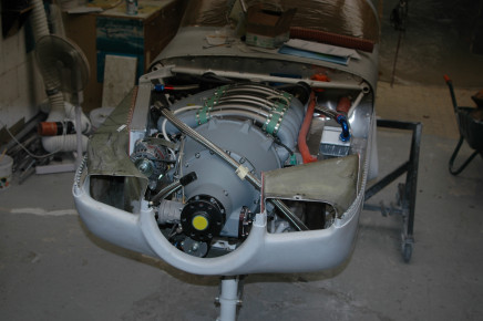
Mistral engine
air duct to the big coolant radiator on the rhs, oil cooler on the lhs, there's a small cooler aft of the exhaust manifold through which the coolant goes on its way to the radiator, and this is my cabin heater - Engine, Glasair III, Glasair
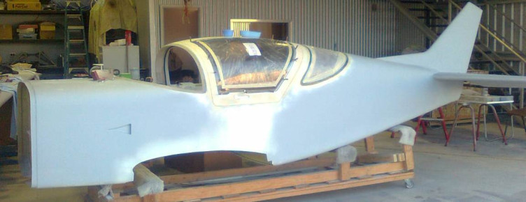
Window Installation
Window installation in the Doors - Glasair, Window, Fuselage
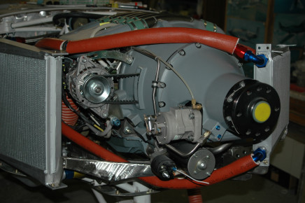
mistral G-300
big coolant radiator on the rhs, the red lines are oil lines to the cooler - Engine, Glasair III, Glasair
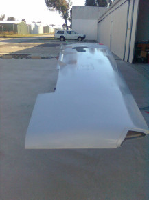
Wing
Wing is primed and ready to have the final fitting of the control surfaces - Glasair, Wing, Controls
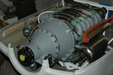
glasair with 300 hp mistral
Engine, Glasair III, Glasair